Here is the a cable size calculator that you can use to engineering work to select the correct cable for your application. This cable sizing tool is easy to use and give the exact minimum size of the cable that you should use for your application.
Also see: Motor FLC calculator | Motor Full load current calculator
What would happen if you select a wrong cable?
If you select the wrong cable size for a long run and one of two things happens: the cable overheats under load, or the far end of your circuit runs at a voltage too low to do useful work. Both are avoidable — and both come down to a single calculation most electricians either skip or estimate by feel.
Our cable size calculator
Here is our free cable size calculator that works backward from what you actually know on a job — the run length, the current, and the supply voltage — and tells you the smallest standard conductor that will keep your voltage drop within limits. Below the calculator you will find the full worked explanation: the formula, three real-world examples, a comparison of copper versus aluminum, and the most common sizing mistakes and how to avoid them.
Why the Run Length Changes Everything
A cable that works fine over 5 metres can cause serious problems over 50 metres — even at the same current. Every conductor has resistance, and resistance is proportional to length. The longer the cable, the more voltage is consumed by the wire itself rather than delivered to the load at the far end.
This is called voltage drop, and it matters for two practical reasons:
- Performance: Motors, VFDs, and electronic equipment are designed for a rated voltage. A motor running at 10% below nominal voltage draws higher current than normal, runs hotter, and wears out faster.
- Safety and compliance: Most electrical codes (IEC 60364, BS 7671, NEC) set a maximum allowable voltage drop of 3–5% for branch circuits. Exceeding this is a code violation on inspected work.
The solution in every case is the same: use a larger conductor. A larger cross-section means lower resistance per metre, which means less voltage lost over the same distance.
The Two Checks You Must Always Do
Cable selection always involves two independent checks. The calculator on this page handles the first one. You must also do the second.
Check 1 — Voltage drop (what this calculator does)
Given the run length, current, and conductor cross-section, calculate the percentage voltage drop and confirm it falls within the allowed limit for your installation. If not, step up to the next standard size until it does.
Check 2 — Current-carrying capacity (ampacity)
A conductor must also be large enough to carry the load current without overheating. The maximum current a cable can carry continuously depends on its insulation type, how it is installed (clipped to a wall, buried in conduit, bundled with other cables), and the ambient temperature. These figures come from tables in your local standard — Appendix 4 of BS 7671 in the UK, NEC Table 310.12 in the US, or IEC 60364-5-52 internationally.
The final cable size is whichever of the two checks demands the larger conductor. On short, high-current runs, ampacity usually governs. On long, low-current runs, voltage drop usually governs. Always check both.
How does the cable size calculator work
The voltage drop across a resistive conductor can be calculated from first principles. Resistance is proportional to length and inversely proportional to cross-sectional area:
R = (ρ × L) / AWhere ρ is the resistivity of the conductor material, L is the length in metres, and A is the cross-sectional area in mm².
The voltage drop across the total circuit (out to the load and back) is then:
Single-phase:  VD = 2 × ρ × L × I / A
Three-phase:   VD = √3 × ρ × L × I / A
The factor of 2 for single-phase accounts for the outgoing and return conductors. Three-phase systems use √3 (≈1.732) because the three phases are 120° apart and partially cancel each other.
Rearranging to solve for the minimum area instead of the voltage drop:
Single-phase:  A_min = (2 × ρ × L × I) / VD_max
Three-phase:   A_min = (√3 × ρ × L × I) / VD_max
Where VD_max is the maximum allowable voltage drop in volts, calculated as: VD_max = supply voltage × (allowed drop % / 100)
Resistivity values used in this calculator:
| Material | Resistivity (Ω·mm²/m) at 20°C |
|---|---|
| Copper | 0.01724 |
| Aluminium | 0.02826 |
The result is a continuous minimum area. The calculator then steps up to the smallest standard conductor size at or above that minimum — because conductors are only available in fixed sizes.
Standard Cable Sizes: Metric (mm²) and AWG
Metric cables follow the IEC standard cross-section series. AWG (American Wire Gauge) is used in North America and some export markets. The two scales do not convert with a simple multiplier — each AWG gauge corresponds to a specific circular mil area.
Standard metric cable sizes (IEC)
| Size (mm²) | Approx. AWG equivalent | Typical use |
|---|---|---|
| 1.5 | 16 AWG | Lighting circuits, signal wiring |
| 2.5 | 14 AWG | Standard 13A socket circuits |
| 4 | 12 AWG | High-current sockets, small appliances |
| 6 | 10 AWG | Cookers, EV chargers |
| 10 | 8 AWG | Sub-main feeds, 3-phase small motors |
| 16 | 6 AWG | Sub-distribution boards |
| 25 | 4 AWG | Larger sub-mains, HV feeders |
| 35 | 2 AWG | Main distribution feeders |
| 50 | 1/0 AWG | Main supply cables |
| 70 | 2/0 AWG | Heavy main feeders |
| 95 | 3/0 AWG | Large industrial supplies |
| 120 | 4/0 AWG | HV distribution, transformer feeds |
| 150 | 300 kcmil | Utility-scale distribution |
| 185 | 350 kcmil | High-power industrial feeders |
| 240 | 500 kcmil | Main LV distribution cables |
Worked Examples
Three examples that cover the most common real-world scenarios. Run each through the calculator above to verify the result.
Example 1 — Single-phase domestic: outdoor socket 40 m from the consumer unit
Given: 230 V single-phase, 16 A circuit, copper cable, 40 m one-way run, 5% voltage drop limit.
Maximum allowable voltage drop: 230 × 0.05 = 11.5 V
A_min = (2 × 0.01724 × 40 × 16) / 11.5
      = 22.07 / 11.5
      = 1.92 mm²
The next standard size above 1.92 mm² is 2.5 mm². Actual voltage drop at 2.5 mm²: (2 × 0.01724 × 40 × 16) / 2.5 = 8.83 V = 3.84%. ✓
Example 2 — Three-phase industrial: 400 V motor 80 m from the panel
Given: 400 V three-phase, 32 A motor FLA, copper cable, 80 m one-way run, 5% voltage drop limit.
Maximum allowable voltage drop: 400 × 0.05 = 20 V
A_min = (√3 × 0.01724 × 80 × 32) / 20
      = (1.732 × 0.01724 × 80 × 32) / 20
      = 76.57 / 20
      = 3.83 mm²
The next standard size above 3.83 mm² is 4 mm². Actual voltage drop at 4 mm²: (1.732 × 0.01724 × 80 × 32) / 4 = 19.14 V = 4.79%. ✓
Example 3 — Long rural single-phase run: 200 m irrigation pump
Given: 230 V single-phase, 20 A pump, aluminium cable, 200 m one-way run, 5% voltage drop limit.
Maximum allowable voltage drop: 230 × 0.05 = 11.5 V
A_min = (2 × 0.02826 × 200 × 20) / 11.5
      = 226.08 / 11.5
      = 19.66 mm²
The next standard size above 19.66 mm² is 25 mm². Actual voltage drop at 25 mm²: (2 × 0.02826 × 200 × 20) / 25 = 9.04 V = 3.93%. ✓
Notice that if copper were used instead, A_min = (2 × 0.01724 × 200 × 20) / 11.5 = 11.98 mm², which steps up to 16 mm² copper — a smaller conductor by cross-section, though likely heavier by cost for a long rural run.
Copper vs Aluminium: Which Should You Use?
Aluminium has about 64% of the conductivity of copper, meaning an aluminium conductor needs roughly 1.6× the cross-sectional area of copper to carry the same current with the same voltage drop. Despite this, aluminium is widely used for long rural runs, overhead lines, and main service cables for one reason: weight and cost. Aluminium is approximately one-third the density of copper and significantly cheaper per kilogram.
| Property | Copper | Aluminium |
|---|---|---|
| Resistivity at 20°C (Ω·mm²/m) | 0.01724 | 0.02826 |
| Relative conductivity | 100% | 61% |
| Density (g/cm³) | 8.96 | 2.70 |
| Typical application | Building wiring, control cables | Overhead lines, main feeders |
| Minimum practical size | 1.5 mm² | 16 mm² (most codes) |
| Jointing requirement | Standard connectors | Bi-metallic or aluminium-rated connectors |
For most building wiring, copper is the practical choice because aluminium below 16 mm² is not permitted by most codes, and aluminium connections require special bi-metallic terminals to prevent galvanic corrosion at joints. For runs over 100 m at higher currents, aluminium becomes worth considering on cost grounds.
Single-Phase vs Three-Phase: What Changes in the Calculation
In a single-phase AC circuit, current flows out through the line conductor and returns through the neutral. The total conductor length the current travels is therefore twice the one-way run. This is why the single-phase formula uses a multiplier of 2.
In a balanced three-phase system, the three phase voltages and currents are 120° apart. This phase difference means the return current is shared across all three phases, and the effective multiplier reduces to √3 ≈ 1.732.
The practical result: for the same one-way distance, current, and conductor size, a three-phase circuit produces approximately 13% less voltage drop than a single-phase circuit. This is one of several reasons three-phase is preferred for long-distance power distribution and industrial motor loads.
Common Cable Sizing Mistakes (and How to Avoid Them)
1. Using the breaker rating instead of the actual load current
A 32 A breaker does not mean the load draws 32 A. Always size the cable for the actual load current — the maximum current the equipment will draw under normal operating conditions. Oversizing the breaker rating can lead to a cable that passes voltage drop calculations on paper but overheats at full load.
2. Entering total conductor length instead of one-way run length
The formula already accounts for the return path. Enter only the one-way distance from the source to the load. Entering the total conductor length will double-count the return path and give a result that is more conservative than necessary.
3. Sizing for voltage drop but not checking ampacity
A cable that passes the voltage drop check may still be undersized for its current-carrying capacity, especially if it is installed in conduit, buried, or bundled with other cables. Always cross-check against the ampacity tables for your installation method.
4. Ignoring the derating effect of cable grouping
When multiple cables are installed together in a conduit or tray, they cannot dissipate heat as efficiently. BS 7671 and IEC 60364 require the rated current to be multiplied by a derating factor (typically 0.65–0.80 for groups of five or more cables). This effectively means a larger conductor is needed than the basic calculation suggests.
5. Assuming copper and aluminium sizes are interchangeable
They are not. A 6 mm² aluminium cable has higher resistance than a 6 mm² copper cable and a lower current-carrying capacity. Always recalculate when switching conductor material.
Frequently Asked Questions
What is the minimum cable size for a 20-metre run at 16 A on 230 V single-phase?
For a 20-metre single-phase run at 16 A on 230 V with a 5% voltage drop limit, the minimum required cross-section is approximately 0.96 mm². The next standard size above this is 1.5 mm², which gives an actual voltage drop of 3.83%. However, check ampacity tables for your installation method before using 1.5 mm² — in conduit or at higher ambient temperatures, a 2.5 mm² conductor may be required on current-carrying grounds.
How do I calculate cable size for a long-distance run?
Use the formula A_min = (2 × ρ × L × I) / VD_max for single-phase, or A_min = (√3 × ρ × L × I) / VD_max for three-phase. ρ is the conductor resistivity (0.01724 Ω·mm²/m for copper, 0.02826 for aluminium), L is the one-way run length in metres, I is the load current in amperes, and VD_max is the maximum allowable voltage drop in volts. The result gives the minimum cross-sectional area in mm². Round up to the next standard conductor size.
What is the maximum allowable voltage drop for a branch circuit?
Under IEC 60364 and BS 7671, the recommended maximum voltage drop is 5% for the complete installation, with many designers targeting 3% for branch circuits to leave headroom for the main supply cable. The US National Electrical Code (NEC) recommends no more than 3% for branch circuits and 5% total including the feeder. Local codes and client specifications may impose tighter limits.
Does cable size affect voltage drop more than cable length?
Both variables have equal and opposite influence in the formula. Doubling the cable length doubles the voltage drop; doubling the cross-sectional area halves it. For a long run where increasing the length is not an option, the only way to reduce voltage drop below the limit is to increase the conductor size or increase the supply voltage.
Can I use aluminium cable for domestic wiring?
Most residential electrical codes, including BS 7671 in the UK, do not permit aluminium conductors below 16 mm² in fixed building wiring. Aluminium is standard practice for overhead service entrance cables and larger sub-main feeders. For branch circuits and socket outlets, copper is required.
What is the difference between cable size and wire gauge?
Cable size in metric countries refers to the conductor’s cross-sectional area in square millimetres (mm²). In North America, conductors are sized by AWG (American Wire Gauge), where a higher gauge number means a smaller conductor — the opposite of what you might expect. AWG 14 is approximately 2.08 mm², while AWG 4/0 is approximately 107 mm². The two systems are not directly interchangeable and must be converted properly when working across standards.
Is this calculator suitable for three-phase motor cable sizing?
Yes, for the voltage drop check. Enter the motor’s full-load ampere (FLA) rating from its nameplate, the line-to-line voltage, the one-way cable run from the distribution board to the motor terminal box, and select three-phase. The calculator will give the minimum conductor size to keep voltage drop within your specified limit. You must also check the result against the ampacity tables for your cable type and installation conditions — motor loads often impose additional derating requirements due to starting current and ambient temperature.
Why does my voltage drop calculation use one-way distance and not total wire length?
The formula already accounts for the return path mathematically. For single-phase, the multiplier of 2 represents the outgoing conductor plus the neutral return. Entering the one-way distance is correct — entering the total conductor length would double-count the return and give an unnecessarily conservative result.
Summary
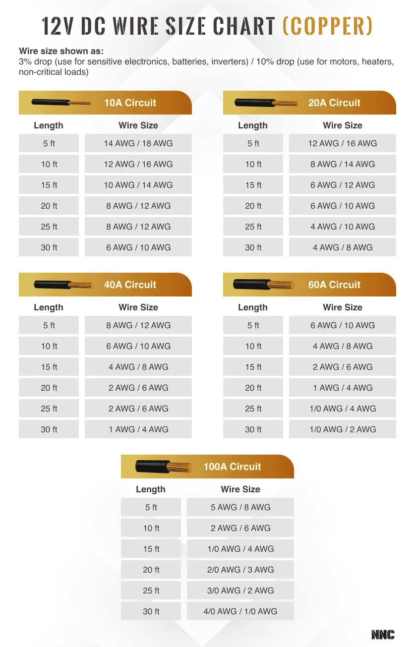
This cable size calculator can ease your work by providing you the exact size of the cable that you should use. Cable sizing for distance comes down to two calculations run in parallel: a voltage drop check and an ampacity check. Calculate the voltage drop side instantly — enter the run length, load current, supply voltage, and maximum allowable drop, and it returns the smallest standard conductor that keeps the circuit within limits.
The ampacity check is your responsibility to complete using the installation-specific tables in your local standard. The final cable size is whichever of the two checks demands the larger conductor.
For questions about a specific installation, leave a comment below. For code-critical commercial or industrial projects, verify all results with a qualified electrical engineer.