4-20mA Current loops are widely used to transmit process variable data such as temperature, pressure, flow rate, level, consistency, speed, etc between the process controllers and the field devices. Transmitters convert these process signals to 4-20mA DC for the purpose of transmitting the signal. This signal can be transmitted to a long distance with little or no loss of signal.
The basic concept of a 4-20mA current loop
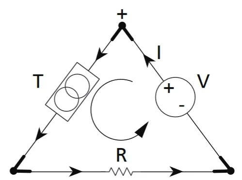
Let us understand the concept of a 4-20mA current loop using a simple three-component triangle.
Let us assume T is a transmitter that converts parameters such as pressure, temperature, etc. to a control signal. R is the receiver of the signal and V is the voltage source that drives current I through the transmitter and the receiver.
Transmitter
The transmitter transmits the current signal that is proportional to the physical property being measured. The level of the loop current is adjusted by the transmitter to be proportional to the input physical property of the sensor(present within the transmitter).
4mA represents 0% of the input property and 20mA represents 100% of the input signal property. It should be understood that the transmitter is not the source of the current. It simply regulates the current flow through it depending on the physical parameters. The power supply to the transmitter and the signal transmission uses the same pair of connection wires.
The transmitter is not the source of the current. It is just a sinking circuit that draws current from the power supply to its output terminals. The magnitude of the current drawn is proportional to the magnitude of the physical parameter being measured. The transmitter needs to be calibrated properly to vary from 4 to 20mA over the range of its physical parameter measured. The real source of power to the transmitter is a power supply.
Power supply
A DC power source supplies the current in a regulated fashion which flows to the transmitter, receiver, and then back to the power supply. The power supply must be chosen in such a way that its minimum output voltage must be higher than the sum of the minimum voltage required by the transmitter to operate, the voltage drop at the receiver and the voltage dropped across the connecting wires. The most common power supply voltage is 24Vdc.
Receiver
The receiver can be an analog input channel of PLC or DCS, controller, or actuator. It passes the current through a resistor and measures the voltage across it. Common resistances used are 250Ω (4-20mA produces 1-5V across the resistor), 500Ω (2-10V), 50Ω (0.2-1V), and 100Ω (0.4-2V). There could be multiple receivers provided the power supply must be sufficient enough to drive current through all the resistances in the receivers.
4-20mA current loop configurations
The following configurations are possible for a 4-20mA current loop depending on the position of the power supply in the circuit.
- 2-wire configuration.
- 3-wire configuration.
- 4-wire configuration.
4-20mA 2-wire configuration
A 2-wired configuration does not have a dedicated power supply. The power is supplied to the transmitter and the output signal is carried in the same wires. They are the most commonly used configuration. Depending on the source of power supply, two types of 2-wire configurations are possible:
- Source type: The signal receiver (such as input channels of PLC, DCS, or other controllers) supplies power to the transmitter.
- Sink type: The signal receiver does not provide power to the transmitter. An external power supply is added to the loop to power them.

4-20mA 3-wire configuration
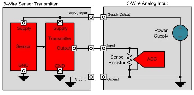
In a 3-wired configuration, the power supply is connected to the transmitter outside the current loop. The transmitter and the receiver share a common ground. It is a simplified version of the 4-wire configuration and allows the use of an external power supply to the transmitter.

4-20mA 4-wire configuration
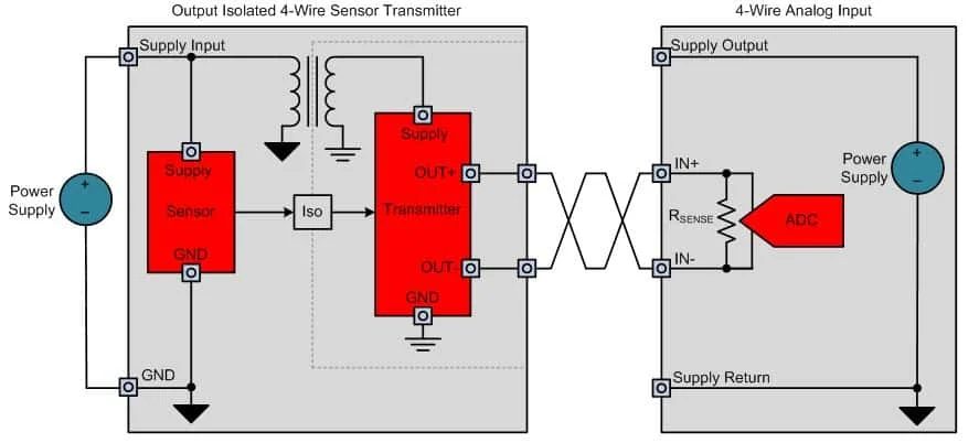
In a 4-wired configuration, the transmitter is powered by an external power supply. Two wires connect the transmitter to the power supply and another two connect it to the analog input channel of the receiver.
Read More: Analog IO and Digital IO
Advantages of a 4-20mA current loop
- A loop 2-wire 4-20mA current loop is the most efficient and cheapest way of transferring data between automation systems and field devices.
- It is very easy to connect and configured.
- The current signals do not degrade with distance.
- The accuracy of the signal is not affected by the voltage drop in the wire.
- Immune to electrical noise.
- In general, the absence of current in the loop is considered a fault. That can be due to instrument failure or wire break.
Disadvantages
- Only one signal can be transferred through the loop.
- In the case of processes with numerous process variables, multiple loops must be created.
The advantages offered by a 4-20mA current loop trivialize its disadvantages. Therefore, it still remains the most popular process control signal used in many industries.


