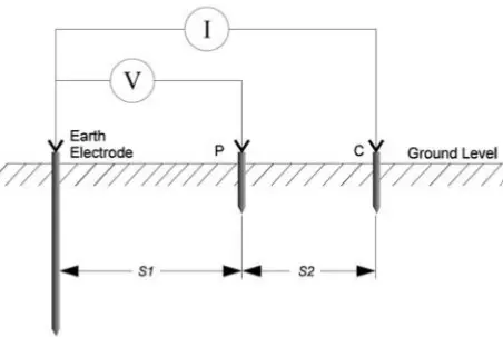
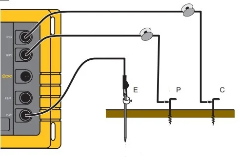
The fall of potential method or 3-point method is the most commonly used method to measure ground resistance. It is used to determine the earth resistance of an existing grounding system. The fall of potential method requires only a minimum amount of calculation and is best suited for small installations. It can be used for testing large grounding systems also.
How to measure earth resistance using the fall of potential method?

This method requires two auxiliary electrodes, in addition to the ground electrode at which the earth resistance is to be measured. Auxiliary electrodes having high resistance can also be used. One of these electrodes is used to pass current to the ground, let us label it as electrode C and the other auxiliary electrode (labeled as P) is used to measure the voltage at any intermittent point between the ground electrode and C. Based on the current applied and the voltage measured, the earth/ground resistance can be calculated by applying ohm’s law.
Position of the current and voltage electrodes
The auxiliary electrode C must be placed far away from the Earth electrode under test such that the auxiliary electrode P lies outside the sphere of influence of those conductors. If the auxiliary electrode, C, is too close, to the Earth electrode, the resistance areas will overlap and there will be a steep variation in the measured resistance as the voltage test electrode is moved.
To make sure that electrode P is out of the sphere of influence of electrode C and the Earth electrode, reposition electrode P to 1 meter towards the Earth electrode and the electrode C respectively and conduct voltage measurements. If there is a significant variation in the readings, the distance between the three electrodes needs to be increased until the readings remain significantly constant.
Also, care should be taken to avoid metal objects present underground short cutting the electrical paths between the electrodes. The test cables used to connect the electrodes to the instrument must also be short.
Steps to measure earth resistance using the fall of potential method
- Disconnect all the connections to the earth/ground electrode including the neutral or any such connections extending to the earth electrode.
- Insert the auxiliary electrodes into the ground at an optimal distance without overlapping the sphere of influence of each other.
- Connect the test probes to the electrodes and measure the resistance. (Modern earth resistance measurement instruments are capable of measuring the resistance directly.)
- Take two more measurements, one by moving the electrode P toward the earth electrode and the other by moving it toward the electrode C to a distance of 1 meter (or 10% of the distance between the earth electrode and the electrode C) from its initial position.
- If the last two measurements have a substantial disagreement, then repeat all the above steps after repositioning the auxiliary to a larger separation distance from the earth electrodes.
- This process continues until a satisfactory result is achieved.
Electrode distance table
| Depth of Earth electrode (m) | Minimum distance between the earth electrode and electrode C (m) | Distance between the earth electrode and electrode P (m) |
|---|---|---|
| 1 | 30 | 15 |
| 2 | 40 | 20 |
| 5 | 60 | 30 |
| 10 | 85 | 43 |
| 20 | 120 | 60 |
| 50 | 200 | 100 |
| 100 | 280 | 140 |
The current passed to the earth electrode during the Fall of potential method or 3-point method for Earth resistance measurements may be Either AC of commercial frequency or DC may be used. When using AC, a stray current of the same frequency may introduce an error. Also, when using DC, DC stray can might introduce a false reading. So, while using DC for the Fall-of-potential method, an accurate reading can be obtained by taking an average of readings taken passing the current in one direction and then reversing the polarity and passing the current in the other direction.
Read more: Are earthing and grounding the same?
The fall of potential method can be used to test systems of any size and is highly reliable and accurate. But it is very time consuming and requires completely disconnecting the electrodes from the system before the test is conducted.

