A transformer is an AC device used to step down or step up voltages. To visualize the current flow and other circuit properties of a transformer, certain assumptions are made, and a conceptual circuit is made, which we can call an ideal transformer. In fact, no transformer is ideal.
What is an Ideal transformer?
A hypothetical model of a transformer, having all the essential properties of a real transformer except the power losses is known as an ideal transformer.
To idealize a real transformer, the following assumptions are made.
- Every transformer has a finite amount of winding resistance, due to which a small amount of voltage drop occurs in the primary and secondary windings. In order to idealize, the primary and secondary winding resistance and the power lost in them are assumed to be zero.
- It is assumed that the flux produced in the primary winding is confined to the core and links the secondary winding (i.e.) there is no leakage flux. But in an actual transformer, there will be a small amount of leakage flux.
- The core is assumed to have infinite permeability, meaning that the magnetizing current needed to establish flux in the core is zero.
- No power is lost in the core in the form of eddy currents or hysteresis.

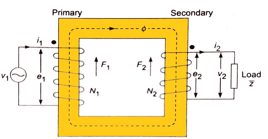
An ideal transformer with N1 turns in the primary and N2 turns in the secondary is shown in the figure. These winding are made over a common magnetic core. It is assumed that the primary and the secondary coils have zero resistance and that the iron core possesses an infinite permeability. The leakage flux and the core losses are assumed to be zero.
Ideal transformer equations
A voltage source v1 is connected to the primary of the transformer.
Where V1 is the RMS value of applied voltage. Initially let us assume that no load is connected to the transformer secondary.
Since the coils have zero resistance,
A varying flux Φ is set up in the core, such that
(1)
Since the leakage inductance is assumed to be zero, the flux Φ produced fully links with the secondary coil. The emf produced in the secondary can be given by,
Since the resistance of the secondary coil is also zero,
(2)
From Equation (1) and equation (2),
In terms of the RMS value of voltage,
The ratio of primary and secondary voltages is known as the transformation ratio or turns ratio and is denoted by the letter ‘a’.
(3)
Therefore, in an ideal transformer, the voltage transformation ratio is the direct ratio of the number of primary and secondary turns.
Now let us consider a load Z2 at the secondary which drains a sinusoidal current i2. Due to the current flow, an MMF is created in the secondary which opposes the flux Φ.
(4)
Since F2 is opposing the mutual flux Φ, the primary drains a current i1, to produce an MMF F1 which is given by
(5)
Since the same flux links the primary and secondary coils,
Hence from equations (4) and (5)
(6)
Comparing equations (3) and (6)
(7)
Hence
(8)
Equation 8 implies that the input power and the secondary power are always equal for an ideal transformer. But this is not the case when it comes to an actual transformer.
In terms of RMS values,
(9)
The above equation implies that the current is transformed in the reverse ratio of the winding turns.
Schematic diagram of an ideal transformer
The below figure shows the schematic diagram of an ideal transformer with the load Z2 connected to its secondary.

The dots in the figure indicate the polarity of the coil. Dividing equation (3) by equation (9),
can be replaced by
can be replaced by
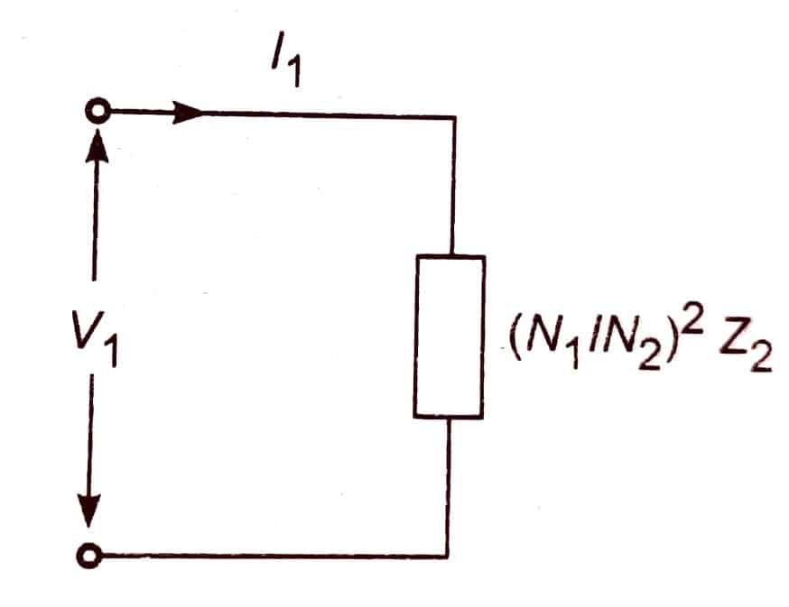
From the above equation, it is evident that the impedance on the secondary side will reflect at the primary side in the square of turns ratio times Z2.
For an ideal transformer, the turns ratio acts as the voltage transformation factor, the inverse of the turns ratio acts as the current transformation factor, and the square of the turns ratio acts as the impedance reference factor, while the power remains unaltered.

when you divide eqn. (3) by (9), don’t you get (N1/N2)^2 on the right? which is a^2
well explained the article in a simple way covering all the aspects. This is the finest articles.
Paul Falstad claims that an ideal transformer is able to pass DC.
https://www.falstad.com/circuit/e-transformerdc.html
I guess it passes my test for passing DC. …
http://tinyurl.com/is-this-realistic
Does his claim fit into your description? Or how does it differ?