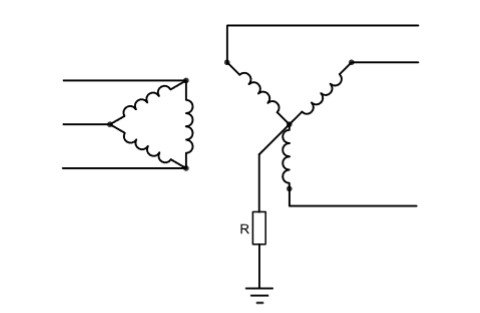
A resistance grounded system or resistance grounded neutral system is one that employs an intentional connection between the neutral and the earth through one or more resistors. In these systems, the damage caused during a ground fault is far less than that caused during a ground fault in a solidly grounded system and the mechanical stress on the equipment is also reduced considerably.
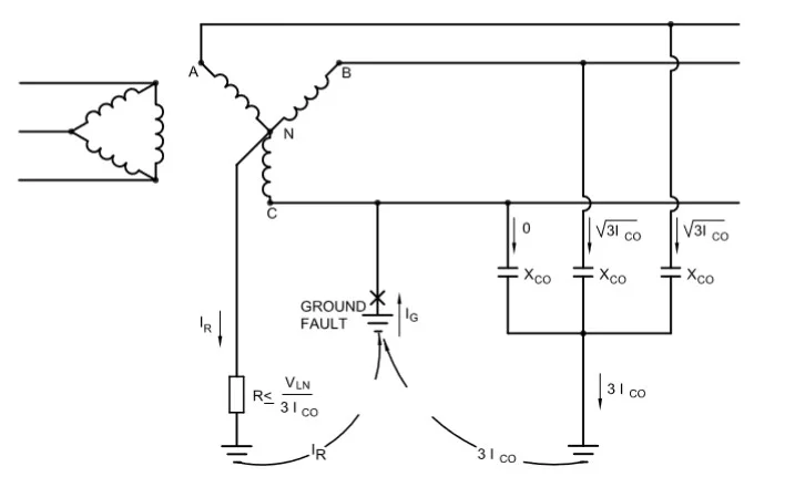
A resistance grounded system is shown in the picture. This resistance commonly has a higher ohmic magnitude than the system reactance close to the point of grounding. This resistance stays in parallel with the line-to-ground
capacitive reactance. Due to its high ohmic value, the parallel circuit behaves more like a resistor than a capacitor.
The following are the reasons for limiting the fault currents by using a resistance neutral grounding system:
- To reduce excessive damage to motors, transformers, switchgear, and other equipment.
- To reduce mechanical stress on circuits.
- To reduce electric shock due to stray ground fault currents.
- To reduce the momentary voltage dips during the occurrence and clearance of faults.
Resistance grounding can be classified into two categories: High resistance grounding and low resistance grounding.
High resistance grounded systems
This system employs a high ohmic value resistance between the neutral and the ground. Typically, in these systems, the fault current is limited to 10A or less in order to avoid the potential damages caused by arcing current larger than 10A in confined spaces. In order to prevent high transient overvoltages, the ohmic value of the resistor is chosen in such a way that the ground fault current through the resistor is slightly greater than or equal to the magnitude of the total capacitance charging current.
High resistance grounding is not recommended for systems over 5kV or those with charging currents of 5.5A or less. The reason is that if a ground fault in any system over 5kV, with no proper ground relaying employed, is left unattended may end up in an electrical hazard. Damage to equipment due to continued high voltage arcing might occur. If the system has a proper ground relaying and if the circuit is opened immediately, there is no problem.
In a grounding resistance, ‘R’ should be chosen to be higher than the total system to ground reactance Xco/3 in order to reduce the tendency of producing transient overvoltages by a pure capacitively grounded system. Since the fault current is often kept to a relatively low level, high-resistance grounding rarely necessitates an immediate clearing of a ground fault. High-resistance grounding typically uses detection and warning instead of an abrupt trip out as its protection mechanism.
During ground faults, the line-to-line voltage is imposed between the phase and the neutral on the two unfaulted phases. It should be noted that this increase in voltage can impose high stress on the insulation of motor windings during sustained line to ground faults. If the fault occurs in the motor winding and the system is still operating with the first fault present then a second ground fault develops in a different phase and serious damage, such as the burning of stator iron laminations, may follow.
Protection scheme for high resistance grounding
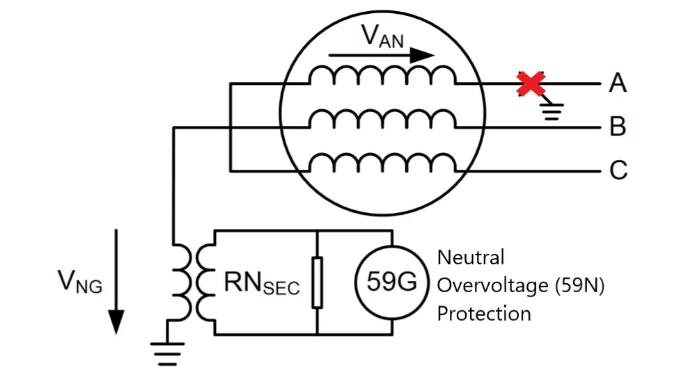
Ground faults in a high resistance grounded system can be detected by using a Neutral Overvoltage (59N) Protection. Under normal operating conditions, the neutral stay at zero potential. In the event of a line-to-ground fault, the potential at the neutral point raises close to the line to a neutral voltage which can be detected using an overvoltage relay.
Advantages of a high resistance grounded system
- Ground fault currents are limited to prevent the damage caused to the equipment.
- Transient overvoltages are eliminated.
- Service continuity is achieved and the first ground fault does not require process equipment to be shut down.
- Minimal phase to ground shock hazards.
- Ground faults can be located using a signal tracing or pulse system.
High resistance grounding is suitable for low voltage without single phase loads and medium voltage systems where operation continuity is the top priority. They are used for grounding auxiliary systems in generating stations.
Low resistance grounded systems
As the name suggests, low resistance is connected between the neutral and the ground to limit the ground fault currents between a few hundred and a few thousand amperes. A low resistance grounded system offers the possibility to obtain satisfactory selectivity and sensitivity with ground relaying connected in the current transformer residual circuit.
The following objectives can be achieved by using a low-resistance grounding:
- Transient voltages can be limited to acceptible levels.
- The magnitude of fault currents can be limited to minimize damage levels.
- Fast and selective relaying is possible upon the proper selection of the characteristics and coordination of the protective equipment.
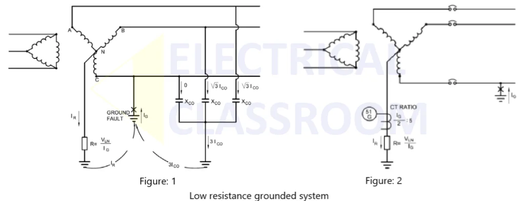
Typically, a low resistance grounded system is preferred when the ground fault current ranges between 100A and 1200A. The value of resistance used for grounding can be calculated using the following formula:
Figure 1 illustrates the flow of current during a line-to-ground fault in this type of system. Generally, the line to neutral voltage is considered for calculating the grounding resistance and Ig is the desired ground-fault current. The combined effect of the capacitive charging current and the system source impedance has very less effect on the ground currents and is hence neglected during the resistance calculation.
Protection scheme for low resistance grounding
One of the major advantages of a low resistance grounding is that it makes sense, immediate and selective clearance of ground faults is possible. One of the methods used for detecting the presence of ground fault is using an overcurrent relay (51G) as shown in figure 2. As mentioned earlier, in the event of a ground fault, the neutral potential raises to a normal line to neutral voltage, and current flows through the neutral resistor. This current is sensed by the overcurrent relay through the CT. The relay then initiates an alarm and opens the circuit breaker.
Another possible method is using core balance current transformers (CBCT). A CBCT surrounds all three lines making the net flux zero when there are no line-to-ground faults. In the event of line to ground faults, the net flux will be no more than zero and the induced current is sensed using a current relay which then opens the circuit breaker.
Advantages of a low resistance grounded system
- Easy fault detection, and immediate and selective clearing of grounding circuits.
- Limited transient overvoltages.
- Limiting severe arc or flash damages from happening.
Low-resistance grounding finds application in medium-voltage systems of 15 kV and below, particularly where large rotating machinery is used.
References:


