Transformers are the most efficient electric machine. A typical transformer is over 99% efficient. The small inefficiency is due to copper losses, core losses-hysteresis and eddy currents losses, stray and eddy current losses occurring in the transformer. These losses result in temperature rise. Various transformer cooling methods are adopted in order to maintain sufficient operating temperature.
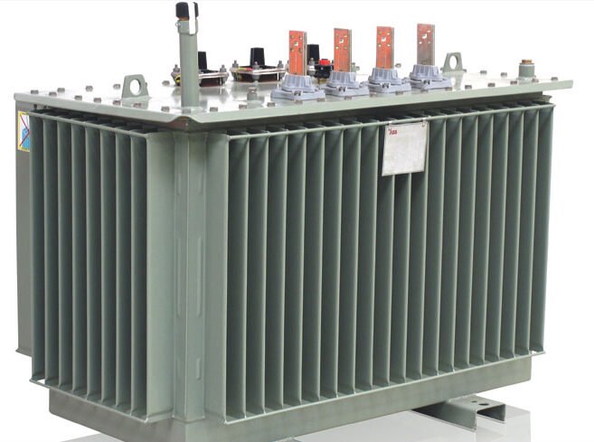
An effective transformer cooling system can improve the transformer capacity by 25% to 50%. According to the cooling methods used, transformers can be classified into air-cooled transformers and oil cooling transformers. In air-cooled transformers are cooled by circulating air over or through the enclosures. Fans may be used to provide forced air. Fins can be added to the transformer enclosures to increase surface area and improve cooling efficiency.
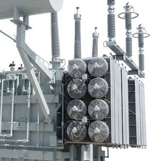
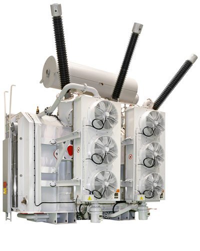
Oil cooled transformers have coil and core submerged in the oil. Natural circulation of oil, forced circulation or water circulation can improve the cooling efficiency. Radiators or fins are fitted to transformer to make cooling more effective. Large oil immersed transformers use circulating oil as well as force air – similar to the one shown in the above picture. Cold water can be circulated inside the transformer housing to improve cooling efficiency.
Modes of heat transfer
Heat transfer mechanism in transformers takes place by three modes viz: conduction, convection and radiation. The heat from the core is directly but from the winding, due to the presence of insulation, heat cannot transfer directly to the oil. Hence the heat from the coil flows through several layers of insulation before reaching the coolant.
The heat transfer from the transformer tank and radiators to the environment occurs through radiation and convection. More the surface area more will the heat transfer by radiation. The heat transfer by radiation depends on the surface emissivity factor. For tanks and radiators painted in grey, the surface effectivity shall be 0.95.
In an oil-immersed transformer, heat from the core and the winding is transferred to oil by convection. As the oil temperature increases, the density of the oil drops. Hence the hot oil moves to the top and is replaced by the colder oil from the bottom. This results in a continuous circulation of oil inside the oil tank naturally and transfers the heat to the external environment through the walls of the tank and radiators.
Transformer coolants
Heat dissipated by the core and the winding is extracted using coolants. Depending on the transformer cooling methods, operational environment, voltages, and several other factors, the choice of coolant can be made. Following are the coolants used in a transformer.
- Mineral oil or transformer oil
- Askarels
- High-Temperature Hydrocarbons
- Silicones
- Esters
- Sulfur hexafluoride
Mineral oil or transformer oil
Apart from enhancing the dielectric strength of coil insulations, transformer oil serves an important purpose of cooling the transformer core and coil. Transformer oil is made from paraffin, naphthenes, aromatics and olefins. Transformer oil is commonly known as hydrocarbon mineral oil. It picks up the heat from the coil and windings and passes it to the tank surface and thus to the environment.
Askarels
Askarels are used in transformers operating in places where flammability is a major concern. Askarels are originally a compound known as polychlorinated biphenyls. Although the compound is inflammable, it can be decomposed by electric arc or fire and may result in formation of toxic materials like furans and dioxins. These compounds are harmful to the environment.
High-Temperature Hydrocarbons
High temperature hydrocarbons are also known as high molecular weight mineral oil. It is a less inflammable compound and is used as an alternative to askarels in distribution transformers. The biggest disadvantage is its high cost and its diminished heat extracting capability when compared to mineral oil or askarels.
Silicones
Silicones are also used as coolant in transformers as they are less flammable. The most commonly used silicone compound is polydimethylsiloxane.
Esters
Synthetic esters are commonly used as transformer coolants in many European countries. They have a high-temperature capability and are biodegradable. But they are expensive than hydrocarbon mineral oil.
Sulfur hexaflouride
In places where transformer oil or any other compounds cannot be used for environmental reasons, pressurized sulfur hexaflouride can be used. It is relatively inert gas and has higher dielectric strength than air. It is used in high voltage transformers where oil cannot be used.
Transformer cooling methods
Oil and air are the primary cooling materials used in a transformer. As mentioned in the beginning of this article, oil serves the dual purpose as an insulator as well as a coolant. In oil immersed transformers, hot oil is circulated through radiators or other heat exchangers which transfers the heat to surrounding air or water which serves as the ultimate cooling medium.
In small distribution transformers, fins or corrugations are made over the tank surface to increase surface area to provide enough cooling surface. The following are the possible ways to transfer from inside of transformers to the environment.
- By natural air circulation.
- By forced air circulation using fans.
- By natural oil circulation due to buoyancy
- Forced oil circulation using pumps.
- Heat exchangers with Forced water circulation.
Oil immersed transformer cooling methods
One or more of the above-mentioned ways are put together for efficient cooling of transformers. The following transformer cooling arrangements can be made to accelerate the heat transfer:
- Oil Natural Air Natural (ONAN) or OA cooling
- Oil Natural Air Forced (ONAF) or FA cooling
- Oil Forced Air Forced (OFAF) or FOA cooling
- Oil Forced Water Forced (OFWF) cooling
- Oil Directed Air Forced (ODAF)/ Oil Directed Water Forced (ODWF)
Oil Natural Air Natural (ONAN) or OA cooling
In small rating oil-immersed transformers, the heat produced can be dissipated directly to the environment without any additional cooling arrangements. It requires a larger dissipation surface in the form of radiators or tubes mounted directly on the tank. The radiator can also be mounted separately in the form of radiator banks supported from the ground.
In Oil Natural and Air Natural transformers, oil circulates itself due to gravitational buoyancy. The heat generated in the coil and the core is passed to the oil by convection. The oil heats up and its specific gravity drops. This causes the hot oil to flow to the surface and cooler oil with higher specific gravity flows downwards. The heat from the oil is then transferred to the transformer surface which then transfers it to the surrounding air.

The cooling efficiency can be improved by installing additional cooling tubes and radiators. Since the heat transfer from the active part to the oil and from oil to the atmospheric air is by natural means, this transformer cooling method is known as Oil Natural Air Natural cooling. The transformer in which this method of cooling is implemented is known as an ONAN transformer.
Oil Natural Air Forced (ONAF) or FA cooling
As the transformer rating increases, the heat produced by the active parts of the transformer also increases. So to enhance the heat transfer between the radiators and the surrounding air, fans are used to blow air onto the radiators. By doing so the heat transfer coefficient is significantly increased. In ONAF transformers, the circulation of oil inside the transformer tank occurs in the same way as in the ONAN transformers. But the only difference is that additional fans are used to force air over the cooling surface to enhance cooling.

The cooling fans are mounted either at the bottom or at the top of the radiators. The temperature of the oil at the top of the radiator will be higher than that at the bottom.While mounting fans on the radiator, their operation should not produce appeciable vibrations on the transformer.
Oil Forced Air Forced (OFAF) Cooling
In ONAN and ONAF transformers, the oil flow inside the transformer is governed by natural factors. To enhance the circulation and rate of heat transfer, an external pump is used in high rating transformers. The pump continuously circulates the oil between the radiators and the tank. Fans are fitted to the radiated to ensure improved airflow and enhance cooling. Unlike ONAF, the fan is mounted on the sides of the radiator.

Oil Forced Water Forced (OFWF) Cooling
In order to improve cooling, oil-to-water heat exchangers are used in OFWF transformers to transfer hot oil. The specific heat capacity of water is more than air. Hence water is used to cool the oil circulated through the heat exchangers. This type of transformer cooling method is very much preferred in hydropower generation stations where sufficient amount of available always.

Oil Directed Air Forced (ODAF)/ Oil Directed Water Forced (ODWF)
In order to improve the heat dissipation rate further, additional arrangements are made in the transformer which directs the circulated oil through predetermined paths. It is used with a forced oil system. The oil entering the tank from the heat exchanger is passed through the windings in a predetermined manner to enhance the heat transfer.
The oil pressure in heat exchangers is always more than the water pressure so that no water leaks into the oil.
Cooling of Dry type transformers
Due to the absence of oil, none of the above transformer cooling methods can be adopted in dry-type transformers. They are normally cooled by the surrounding air naturally. For dry-type transformers fitted in cabinets, proper ventilation are provided for air circulation. The following two transformer cooling methods are adopted in dry-type transformers.
- Air Natural (AN) cooling – Cooled by surrounding air. Heat transfer by natural convection.
- Air Forced (AF) cooling – Forced sir circulation using fans and blowers.
Transformer cooling class letter description
| Code Letter | Description |
|---|---|
| First Letter | Cooling medium (Internal) |
| O | Liquid with a flash point less than or equal to 300°C |
| K | Liquid with a flash point greater than 300°C |
| L | Liquid with no measurable flashpoint |
| Second Letter | Cooling mechanism |
| N | Natural convection through cooling equipment and windings |
| F | Forced circulation through cooling equipment, natural convection in windings |
| D | Forced circulation through cooling equipment, directed flow in man windings |
| Third Letter | Cooling medium (External) |
| A | Air |
| W | Water |
| Fourth Letter | Cooling mechanism |
| N | Natural convection |
| F | Forced circulation |


-Is the ODWF assembly installed inside the transformer tank or outside it?
– Is the ODWF assembly Is in addition to the OFWF assembly and operate together or the transformer is equipped with only one of the two cooling systems?
ODWF (Oil-Directed Water-Filled) is a specific cooling method used in certain types of transformers. In an ODWF transformer, the cooling process involves the circulation of both oil and water within the transformer tank to dissipate heat generated during operation.
The ODWF cooling method typically employs a heat exchanger system. Here’s a general overview of how it works:
Transformer Tank: The transformer tank contains both oil and water.
Heat Generation: During operation, the transformer’s core and windings generate heat. This heat is transferred to the surrounding oil.
Oil Circulation: The heated oil flows from the core and windings to the upper part of the tank. It then enters a heat exchanger, where heat is transferred to the circulating water.
Water Circulation: The water, which absorbs heat from the oil, is circulated by a pump through the heat exchanger. As it passes through the heat exchanger, it absorbs the heat from the oil, effectively cooling it down.
Cooling Water: The heated water is then directed to an external cooling system, such as a cooling tower or a radiator, where it dissipates the absorbed heat to the surrounding environment.
Cooled Oil: After transferring its heat to the water, the now-cooled oil returns to the lower part of the transformer tank, ready to absorb more heat from the core and windings.
By combining the properties of both oil and water, the ODWF cooling method provides efficient cooling for the transformer. The oil helps to transfer heat from the core and windings to the water, and the water, in turn, carries the heat away from the transformer through the cooling system.
It’s worth noting that ODWF is just one of several cooling methods used in transformers, and the specific cooling technique employed can vary depending on the transformer design, size, and application requirements.