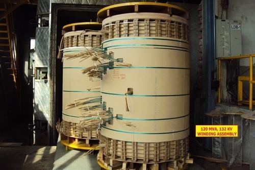
Transformer windings constitute the electrical circuit of a transformer. They are made up of current-carrying conductors wound around the core. The primary windings form the input to the transformer and the secondary windings form the output. The construction of the transformer windings should be stable enough to ensure safe operation. It should also be mechanically strong to withstand the faults. A suitable type of transformer windings is selected depending on the VA rating of the transformers.
Winding conductors
Winding ratio determines the voltage transformation capability of a transformer. The windings must be properly insulated, supported and cooled for fault free operation. Copper or aluminum conductors can be used to make transformer windings. Aluminum is lighter than copper but has 50% lesser conductivity than copper. It is cheaper than copper.
On the other hand, copper has a very good mechanical strength and twice the conductivity of aluminum. Normally, rectangular conductors are used in transformers in order to ensure the maximum utilization of transformer windings. Apart from the current carrying capacity, mechanical forces during short circuits influences the dimensions of the windings.
Types of transformer windings
Some commonly used types of transformer windings are:
- Layer windings
- Helical windings or spiral winding
- Disc windings
- Foil windings
Layer windings
Layer winding is done by axially arranging turns of insulated conductor along the windings. Turns are wound next to each other without any space in between them. Layered windings can be single or multilayered. The single-layered winding has only one turn of winding around the core limb.
In multilayered windings, several layers of insulated conductors are wound on above the other. These layer are separated by solid insulation, oil ducts or the combination of both. Multilayered windings are chiefly used for small and medium size transformers.
Helical winding or spiral winding
Helical winding is otherwise known as spiral winding. It is a variant of multilayer winding and consists of several conductors in parallel to form a single turn. The parallel conductors are wound along the axial direction with spacers inserted between the adjacent turns. This type of construction resembles a corkscrew. Helical windings are used in low voltage and high currents where current flow in several parallel conductors. The voltage induced in each turn of each strand remains the same.
The magnetic field linking each parallel conductor may not be the same. Uneven flux distribution between the conductors gives rise to eddy currents in them. In order to avoid that, the position of each conductor is varies so as to equalize the magnetic field linking them. This technique is known as transposition of conductors and it is very effective in minimizing the eddy currents in the conductors.
Helical windings are mechanically robust. They have a very good space factor and are easy to manufacture.
Disc winding
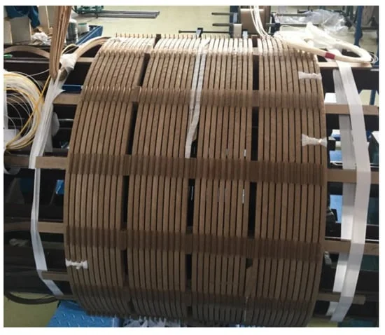
Disc windings are constructed by connecting several discs of conductors in series. At first, a disc is made by winding multiple turns of insulated conductors one over the other and then several such discs are connected in series to form disc winding. Each disc is seperated from the adjacent disc using spacers. The disc can be formed by winding a single conductor or several conductors in parallel.
The major difference between a disc winding and helical winding is that the helical winding consists of only one turn of parallel conductor per disc while the disc winding consists of several turns per disc. In most core type transformers rated above 25kV, disc type windings are preferred. Like helical windings, disc windings are also mechanically robust.
Foil Windings
Foil windings are made by using thin sheets of copper or aluminium. A thin sheet of insulated sheet is wound multiple times to form a multilayer spiral windings. The winding can be formed either using a single sheet or multiple sheets in parallel wound on the flat side. They are used in high capacity transformers with current ranging from 12 to 600 A.
Transformer winding conductors
Conductor materials
The primary material used for transformer windings is aluminium and copper. Copper has higher conductivity and mechanical strength whereas aluminium is lighter and cheaper than copper. For large transformers, copper windings are normally (to make the size of transformer smaller) used whereas, in small and medium-sized transformers, aluminium conductors are commonly used.
Comparison of the general properties of copper and aluminium conductors
| Property | Unit | Copper | Aluminium |
|---|---|---|---|
| Resistivity at 20°C | Ω mm2 / m | 0,0175 | 0,0285 |
| Electrical conductivity at 20°C | m / Ω mm2 | 57,1 | 35,4 |
| Temperature Coefficient of electrical resistance at 20°C | – | 0,00427 | 0,0044 |
| Thermal conductivity | W / m °C | 393 | 203 |
| Specific heat | W sec / kg °C | 385 | 920 |
| Melting point | °C | 1084 | 658 |
| Boiling point | °C | 2595 | 2060 |
| Specific weight | kg / m3 | 8900 | 2700 |
| Tensile strength | kgf / mm2 | 24 | 10 |
| Elastic limit | kgf / mm2 | 6 – 8 | 2 – 5 |
| Coefficient of linear expansion at 20°C | – | 17 x 10-6 | 24 x 10-6 |
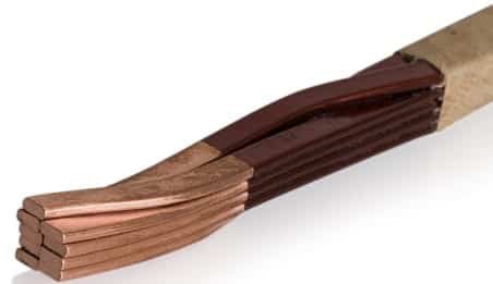
In order to ensure the optimal utilization of available space, rectangular conductors are used usually. Even for small core type transformers, the small circular wire used for winding is often flattened on both sides to improve the space factor. The conducting area can also be increased by using two or more parallel conductors. This can in turn help in reducing eddy currents in the conductor. While using parallel conductors, each strand is insulated from each other by enamel coating or paper lapping.
Transposition of windings
As mentioned earlier, in helical windings and disc type windings where several parallel conductors are used, the parallel conductors are continously transposed in order to minimize circulating currents. By transposition, the parallel conductors will receive the same magnitude of induced voltage.
Parallel conductors in a transformer windings can be transposed in several way. Few methods are shown below:


Kindly could you explain the high seriece capacitance winding
with my best regards
Kindly could you explain the high seriece capacitance winding
with my best regards