An autotransformer is a single-winding electrical transformer. It is also known as variac or dimmer stat. It is made of a single-winding coil. This single-winding setup makes them cheaper, more efficient, and have better voltage regulation than normal transformers. They are much more useful in cases in which the voltage ratio is less than 2 and the electrical isolation of winding is not essential.
Note: The term ‘Auto’ in ‘autotransformer’ does not refer to automatic output voltage variation.
Parts of an autotransformer
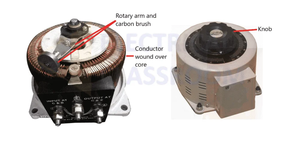
An autotransformer consists of three basic parts: core, winding, and moving contact-knob arrangement. An external casing is also provided to prevent direct access to the conducting parts.

Core
The core is made of high-quality Cold Rolled Grain Oriented (CRGO) silicon steel in order to minimize core losses. The core could be laminated, split, or toroidal type
Winding
As said earlier, autotransformers have a single copper conductor wound over the core which acts as the primary and secondary.
Moving-contact-knob arrangement
A rotary arm-like arrangement with a carbon brush at its tip and a knob at the top is present in autotransformers. The carbon brush slides over the windings when the knob is rotated. Smooth control of voltage can be attained with the help of the sliding brush.

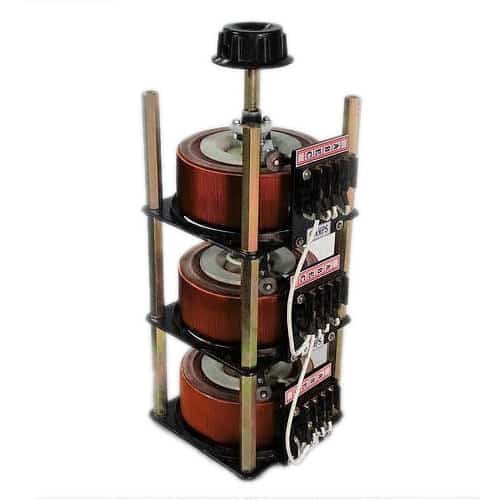
In the case of three-phase autotransformers, three single-phase autotransformers are arranged one above the other, as in the picture above, and controlled by a single knob.
Working principle
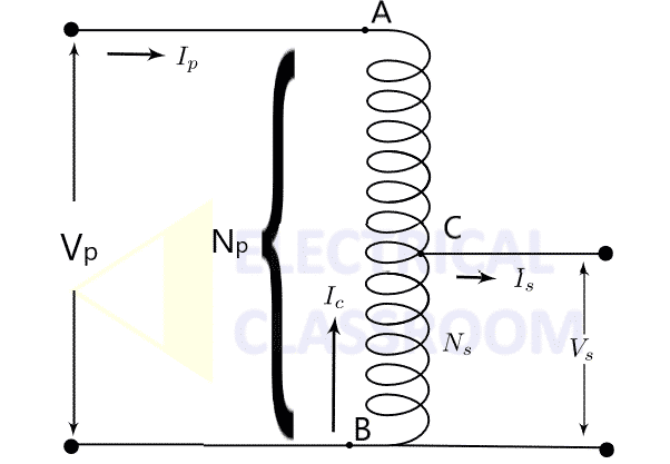
As mentioned earlier, in an autotransformer single winding serves as both primary and secondary. Terminals A and C acts as the input (primary) and terminals E and C act as the secondary. E is connected to the sliding carbon brush.

A part of the energy transfer between the primary and the secondary is through conduction and the rest is through induction. In the schematic shown below, Let Np be the total number of turns wound over the transformer core, and the brush is moved to point C to obtain a secondary turns Ns. Vp and Vs are the voltage measured across the primary and secondary currents respectively. Ip and Is are the primary and secondary currents.

The voltage and current transformation ratio (turns ratio) are the same as that of the two-winding transformer.
The number of turns between points A and B is Np, and the number of turns between A and C is (Np-Ns). Since all the turns link the same flux in the transformer core,
The turns ratio ‘a’ can be varied by moving the carbon brush through the winding and changing the position of point C.
Turns ratio, a
The turns ratio of the upper part of the transformer is given by
Copper savings in autotransformer
Copper conductor contributes to the larger part of the manufacturing cost of a transformer. As the primary and secondary coils of the autotransformers share the same winding, huge cost savings can be achieved.
The weight of the copper winding depends on the length and thickness of the conductor used. Therefore it is proportional to the number of turns of copper used in the transformer.
The weight of copper ∝ (length of cu. wire × cross-sec. area of cu. wire)
The area of the cross-section of copper wire is directly proportional to the amount of current it can conduct.
Therefore, the weight of copper, N ∝ N × I
The weight of copper (WAT) needed for an autotransformer is proportional to:
WAT ∝ (Np – Ns).Ip + Ns.(Is – Ip)
(i.e.) WAT ∝ Np.Ip + Ns.Is – 2Ns.Ip
Since Np.Ip = Ns.Is,
WAT ∝ 2(Np – Ns).Ip ——— Equation (1)
Now, let us calculate the weight of copper (WTW) required for a two-winding transformer.
WTW ∝ Np. Ip + Ns. Is
Since Np.Ip = Ns.Is,
WTW ∝ 2Np.Ip ——— Equation (2)
Dividing equation (1) by equation (2),
This means if the turns ratio is 2, the weight of copper required for an autotransformer is half of that required for two winding transformers.
Read More: Transformer turns ratio
Applications
- Autotransformers are widely used in laboratories to obtain variable AC voltage for lab apparatus.
- They are used to start induction and synchronous motors.
Advantages and disadvantages of autotransformers over two winding transformer
Advantages
- For the same VA rating, an autotransformer requires less copper and less core material.
- Also, it requires a less exciting current, has an ohmic loss, and is lighter as compared to a two-winding transformer.
- Autotransformers have higher efficiency and lower leakage impedance than two-winding transformers.
- They have better voltage regulation than two-winding transformers.
Disadvantages
- They are preferred for a voltage ratio of less than 2.
- A break in the part of the winding that is used as both primary and secondary will result in the transformer acting as an inductor in series with the load.
- Autotransformers do not isolate primary and secondary circuits. Hence any failures in the transformer can result in the application of full primary voltage to the load.
- Due to lesser impedance, the short circuit current in an autotransformer is higher than that in two winding transformers.
Further reference: Sen, P. C. (2013). Principles of Electric Machines and Power Electronics. United Kingdom: Wiley.
Read more about transformers: https://www.electricalclassroom.com/electric-machines/

Your articles are usually easy to follow with well worked examples. Keep up the good work!