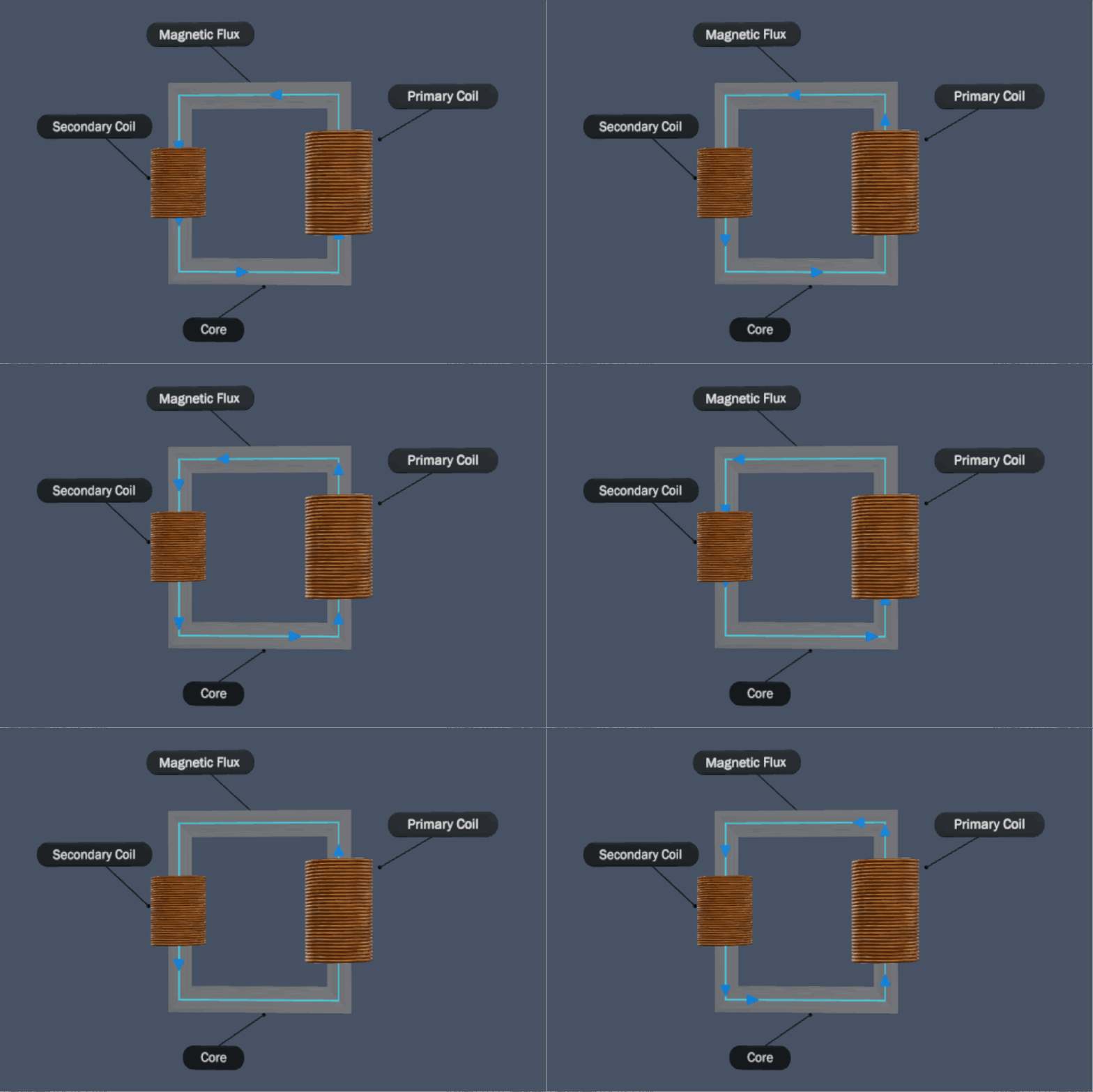
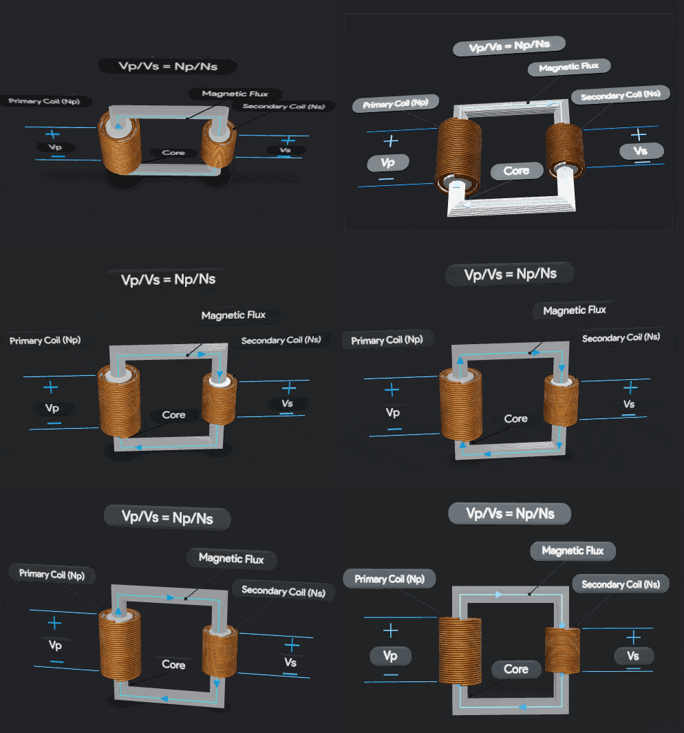
An electric transformer is a device used to step up and step down ac voltages. This article will help you understand their basic concepts, construction, the principle of operation, tests conducted on them, and their classification.
During earlier days, DC power was generated close to load stations and distributed. The invention of the transformer resulted in recent advancements in the power generation, transmission, and distribution sectors. They made bulk power generation and long-distance AC power transmission possible. Today power is transmitted at up to 765kV with minimum power losses and higher efficiency.
- What is an electric transformer?
- Principle of operation of transformers
- Who invented the electric transformers?
- Ideal Transformer
- Turns Ratio
- Construction of transformer
- Buchholz Relay
- Losses in a transformer
- Equivalent Circuit
- Voltage regulation of the transformer
- Classification of transformer
- Distribution transformers
- Potential transformers
- Current transformers
- Testing of transformer
- Why are they used in the power system?
What is an electric transformer?
An electric transformer is a piece of equipment that is designed to change the magnitude of AC voltage in a circuit, without altering the frequency, and at a minimum power loss. Power is delivered from its input side to its output side by the process of electromagnetic induction.
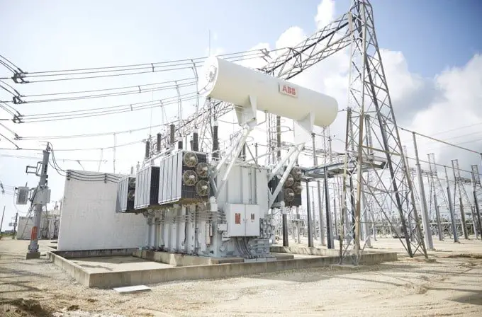
They are used to transmit power generated at a remote location to the consumer efficiently at the required voltage. They are available in various sizes and ratings from those huge ones in a substation to those tiny ones in an electronic board.
The Principle of operation
Transformers work on the principle of mutual inductance and Faraday’s law of electromagnetic induction. The flow of an alternating current through a coil produces an alternating magnetic field. When another coil is brought in contact with the alternating magnetic field, voltage is induced in that coil. According to Faraday’s law, the magnitude of the induced voltage depends on the rate of change of magnetic flux linking the second coil and the number of turns.
ε =-N dΦ/dt
When it comes to transformers, the rate of change of magnetic flux between the coils is almost the same. Therefore, the induced voltage depends on the number of turns of the coils. Hence, the higher the number of turns of the coil, the larger will be the induced voltage.
A typical transformer is made up of a set of primary and secondary coils wound over a laminated soft iron core. The iron core acts as a low reluctance path for the flow of magnetic flux.
When an alternating voltage is applied to the primary coil of the transformer, an alternating flux is generated which links the secondary coil through the laminated iron core and induces an alternating voltage in it. The magnitude of the induced voltage depends on the ratio between the number of turns of the primary coil and the number of turns of the secondary coil.
Who invented the electric transformers?
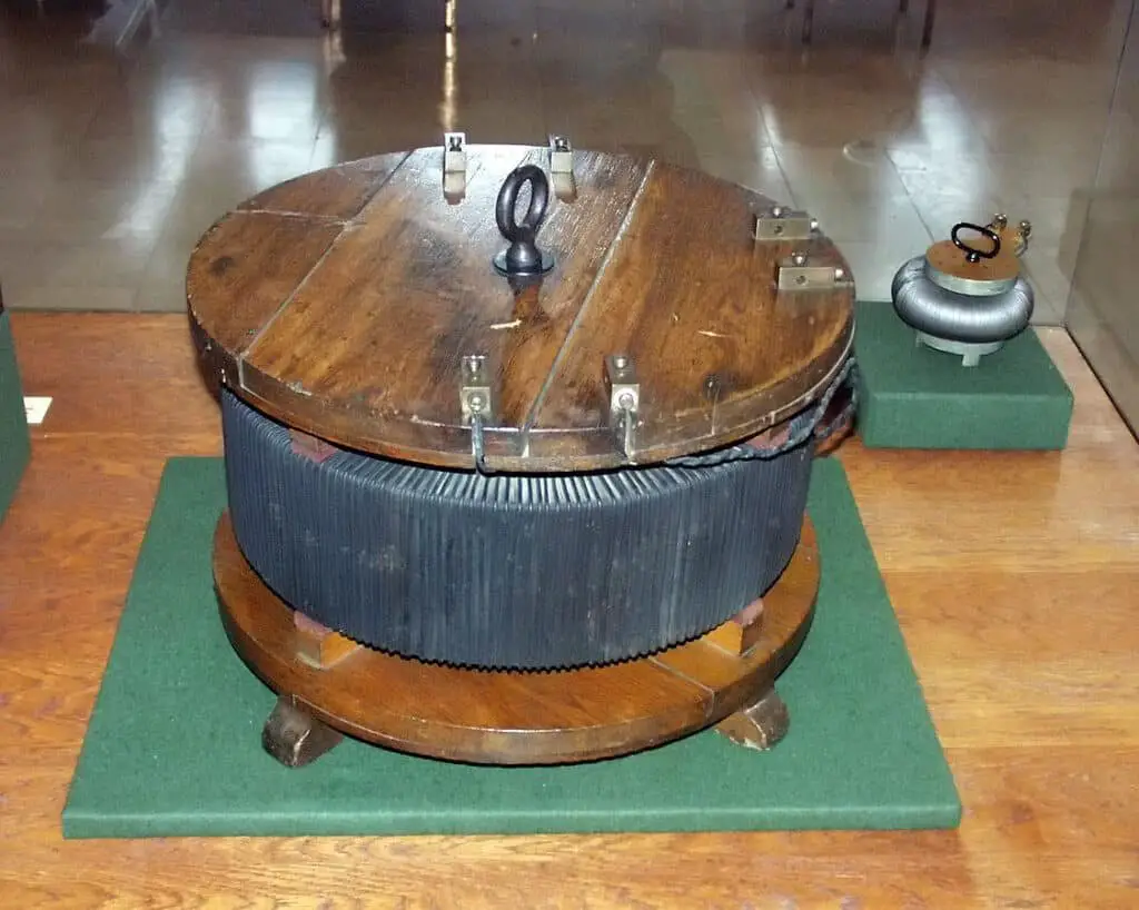
The most primitive version was invented by Faraday. In 1884, three Hungarian engineers, Károly Zipernowsky, Ottó Bláthy, and Miksa Déri, designed the first high-efficiency called ZND transformer. It led to development of new and highly efficient modern design. The first three-phase transformer was designed by Mikhail Dolivo-Dobrovolsky.
Components in a transformer
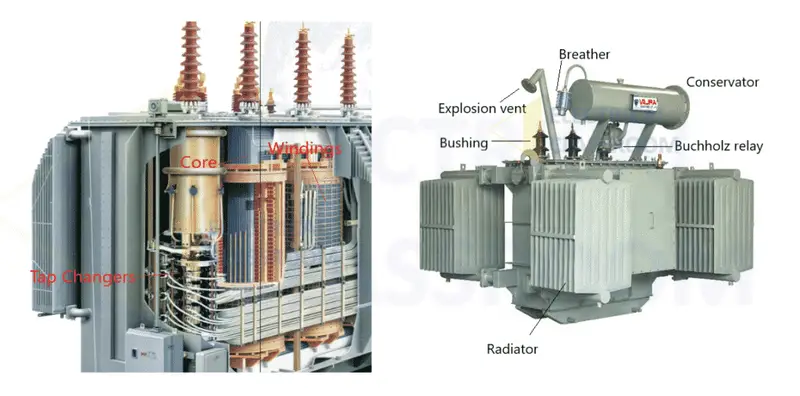
Irrespective of design types, the following are the major components of a transformer. Learn more about various parts in detail.
- Core
- Winding
- Insulation
- Conservator
- Transformer oil
- Buchholz Relay
Core
A core is a structure over which primary and secondary are wound. It supports the windings as well as provides a low reluctance path for the magnetic flux linking primary and secondary winding. It is made up of high-permeability silicon steel lamination to reduce core losses. The core must be designed in such a way as to minimize the eddy current and hysteresis losses.
Winding
Electric transformers have two sets of windings, a low-tension winding, and a high-tension winding. Several turns of copper conductors bundled together to form a winding. The size of copper conductors depends on the load current. Most of the time windings are referred to as primary winding and secondary winding.
Normally the winding to which the input voltage is connected is known as the primary winding and the winding to which the load is connected is known as the secondary winding. Sometimes, based on the level of voltage applied to them, they are referred to as high-tension winding and low-tension windings.
Insulation
Windings are insulated from each other and the core. Insulation failures might result in short circuits and can cause severe damage. Hence greater care is taken on the insulation part during the design phase. Varnish, kraft paper, Cotton cellulose, and Pressboard are the most widely used winding insulation materials.
Transformer oil
In oil-immersed transformers, the oil serves the dual purpose of insulation and cooling. It has a high breakdown voltage, high resistivity, and high dielectric strength. It extracts heat from the windings and core and helps in reducing losses and improves efficiency.
Buchholz Relay
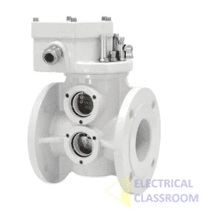
Buchholz relay is a protection device used to protect a transformer from internal faults such as short circuits, overheating, and oil leakages. It is an oil-actuated relay used to sense the faults occurring in the windings and core and trigger the alarm circuit and trips the circuit breaker and interrupts the power supply. Read more about Buchholz relay detail: Buchholz relay – Principle of operation
Ideal Transformer
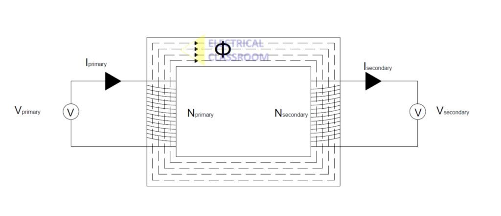
An ideal transformer is an imaginary device, having zero losses, infinite permeability to magnetic flux, and 100% efficiency. Since the same amount of flux is linking the primary and the secondary winding, the ratio of applied voltage (Vprimary) and induced voltage (Vsecondary) must be proportional to the ratio of number of turns in the primary to the number of turns (Nprimary) in the secondary winding (Nsecondary).
Vprimary / Vsecondary = Nprimary / Nsecondary
In an Ideal transformer, input power is equal to output power.
Vprimary / Vsecondary = Isecondary / Iprimary
In a real transformer, the voltage induced per turn is given by the following equation:
E/N = K.Φm.f
where K is a constant, Φm is the maximum value of total flux in Webers linking that turn and f is the supply frequency in hertz.
Step-up & Step-down Transformer
In step-up transformers, the secondary winding has more turns than the primary winding. Also, the voltage at the secondary shall be higher than the primary voltage (depending on the turn ratio). They are used to increase transmission voltage to reduce transmission losses. They can be found in generating stations and are commonly known as power transformers.
In a step-down transformer, the number of turns of coil in the secondary winding is lesser than on the primary side, and hence the voltage. They are used to reduce the voltage at the distribution side of the power system.
Turns Ratio
Turns ratio ‘n’, is a number denoting the ratio of the number of turns of the conductor in the primary coil to that of the secondary coil. The transformer ratio is also known as the voltage transformation ratio. This tells about the voltage available at the secondary terminals for an applied primary voltage.

NP – Number of turns of the conductor in the primary coil.
VP – Applied Primary voltage.
NS – Number of turns of the conductor in the secondary coil.
VS – Transformed voltage measured at the secondary.
Losses occurring in a transformer
The losses occurring in a transformer are classified into winding loss and core loss. Winding loss occurs due to resistance offered by the conductor. It is proportional to the square of the current flowing through it. Using thick copper conductors minimizes the resistance to current flow and reduces winding loss. Core losses are due to eddy currents, formed in the core, and the hysteresis effect. Core losses, also known as iron losses, are always constant and are independent of load. Using laminated soft iron core and thick conductors can help in reducing core losses and improve their efficiency.
Equivalent Circuit
It is a theoretical circuit that represents a transformer and its physical behavior. This circuit shown below represents its electrical parameters from which losses and voltage drops can be easily calculated.
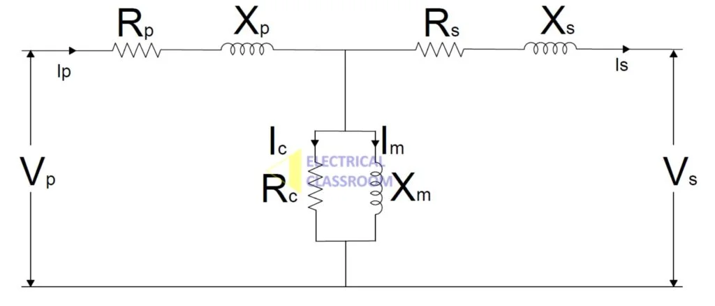
VP – Primary voltage or applied voltage
IP – Primary current
RP – Resistance offered by the primary winding
XP – Reactance offered by the primary winding
IC – Current component contributing to core losses
RC – Resistive component contributing to core losses
IM – Magnetizing current
XM – Magnetizing reactance
Vs – Secondary voltage or applied voltage
Is – Secondary current
Rs – Resistance offered by the secondary winding
Xs – Reactance offered by the secondary winding
Note:
The above equivalent circuit is a generalized form of an equivalent circuit for an ideal transformer with a turns ratio of 1:1 and without referring to either the primary or the secondary side.
Learn more: Equivalent circuit and Phasor diagram of a transformer
Voltage regulation of the transformer
How accurate the voltage transformation occurs in the transformer when the load varies from no load to full load is dictated by their voltage regulation. It is calculated using the following formula:
Where,
Esec-noload – Voltage measured at the secondary at no load.
Esec-fullload – Voltage measured at the secondary at full load.
Classification of transformer
Transformers are available in various types, shapes, and forms. Based on where they are used and various other parameters such as type of supply, their application, type of construction, cooling method, operational voltage, duty type, the shape of the core, etc.
Classification based on the type of power supply: Three-phase and single-phase device.
Classification based on the type of construction: Core type and Shell type transformer.
Classification based on cooling method: Dry-type or natural air-cooled, Oil cooled- Oil Natural Air Natural (ONAN), Oil Natural Air Forced (ONAF), Oil Forced Air Natural (OFAN), Oil Forced Air Forced (OFAF), Oil and Water-cooled – Oil Natural Water Forced (ONWF), Oil Forced Water Forced (OFWF)
Classification based on purpose: Distribution, Instrument (potential and current), isolation, grounding, radio frequency, phase-shifting and autotransformers, and tesla coil.
Learn more: Types of electric transformers.
Tests conducted in a transformer
The following tests are conducted to ensure the proper functioning of the device:
- Winding resistance test.
- Insulation resistance test.
- Transformer resistance test.
- No-load test – Open circuit test.
- Short circuit impedance test – Short circuit test.
- Temperature rise test.
- Polarity checks.
- Dielectric test for oil.
- Noise Level tests
Why are they used in the power system?
An electric transformer can be considered the most important component in a power transmission and distribution network. It performs the duty of improving transmission efficiency and reducing losses and transmission costs by stepping down voltages. The power station generates power at a voltage of 11kV to 28kV at 50Hz. To reduce transmission losses, the voltage is stepped up to 220kV or more and transmitted. At the distribution substation, it is again stepped down to 33kV or 11kV upon the requirement and supplied to industries. It is again stepped down at the domestic consumer end to low voltage loads of the consumer.
By stepping up the voltage, the load current flowing through the transmission lines is reduced. Reduction in load current results in the reduction of copper loss (I2R loss) and the size of the conductor used for power transmission. Hence, the cost of power transmission as well as its efficiency is improved. Hence they improve the system efficiency, and reliability and reduce power transmission costs.
References:
- Toroidal Line Power Transformers. Power Ratings Tripled.
- Lane, Keith (2007) (June 2007). “The Basics of Large Dry-Type Transformers”. EC&M. Retrieved 29 January 2013.
- Electromechanical systems, electric machines, and applied mechatronics By Sergey Edward Lyshevski.
