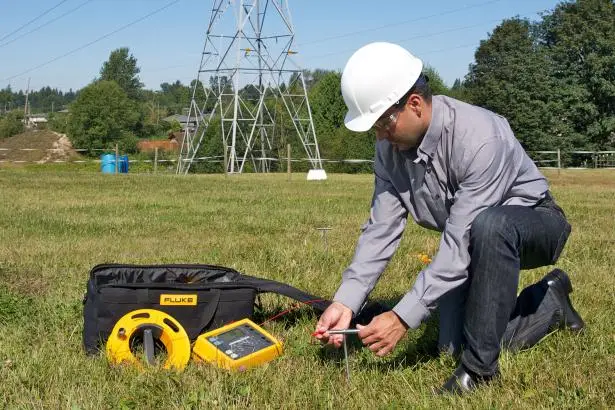
It is vital to maintain good ground in a system. In order to ensure that, ground resistance measurements and tests are conducted on existing earth electrodes at periodic intervals after their installation. This ensures the resistance in the ground is at an acceptable level and is maintained. Here are the different methods of ground/ earth resistance measurements on existing systems.

Earth resistance measurement/ test methods
To ensure good earth any one of the following ground/earth resistance measurements conducted on existing systems:
- Fall of potential method or 3-point method.
- Induced Frequency Testing or Clamp-On Testing or stakeless method
- Attached rod method technique
- Star-delta method
- Dead earth method or Two Electrode method.
- Slope Method
Effective ground resistance testing involves the use of proper, accurate, and reliable measurement instruments with built-in noise suppression features as well as following proper test procedures. His article can give you a basic idea of how to conduct earth resistance tests.
Fall of potential method or 3-point method
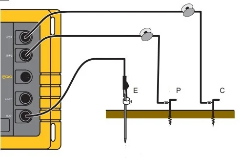
In order to test the resistance using this method, two test electrodes and an earth resistance tester are required. One of these electrodes is used to inject current into the ground and the other (potential electrode) is used to check the voltage. The current electrode is inserted at a distance from the existing earth electrode to a depth equal to the depth of the earth electrode.
The potential electrode is inserted between the existing earth electrode and the current electrode to the same depth such that it is out of the spheres of influence of the other two electrodes. A modern earth tester can be used to test the resistance. Conventionally, the voltage between the potential electrode and the earth electrode, and the earth resistance is calculated using ohm’s law:
Read more: Understand the Fall of potential method or 3-point method in detail
Induced Frequency Testing or Clamp-On Testing
The 3-point method requires all the connections to the earth electrode removed before conducting the test whereas the induced frequency tests can be conducted on a live system. Clamp-On Testing is a simple earth resistance measurement method that does not require additional test electrodes. Therefore this method is also known as the stakeless method of earth testing.

To measure the earth resistance, two clamps are placed around the electrode at which the ground resistance is being tested. One of the clamps induces voltage to the electrode and the other measures the current flowing through the ground. Based on the current and voltage measurements the ground resistance can be calculated using Ohm’s law.
This method is very effective if there must be a series-parallel resistance path. For example, for a system having a parallel earth network in which we want to measure the earth resistance Rx in parallel with n earth electrodes, the tester is clamped over the electrode under test. When a voltage is induced, all current flow through the test electrode and divides and divides between the remaining electrodes in parallel.
The earth resistance can be calculated using the following formula:
Rloop = E / I = Rx + (R1 // R2 // R3…//Rn) + Rearth-wire
Where E is the applied voltage, I is the current measured, Rx is the resistance sought, R1, R2, R3…Rn are the resistance of electrodes in parallel and Rearth-wire is the resistance of the earth wire.
The biggest advantages of the clamp-on method over the fall of potential method are that it is quicker, simple and no additional test electrodes have to be driven and the ground rod does not have to be disconnected from the system.
Attached rod technique (ART)
The attached rod technique uses a similar concept to the fall-of-potential method while maintaining the possibility to conduct the test without disconnecting the earth electrode while taking additional measurements. This method uses an earth leakage clamp meter to take additional current measurements.
The current and potential electrodes are inserted into the ground at the right distances (as that is done in the fall of potential method). At first, the total resistance of the entire system is measured using a typical fall of potential configuration.
Secondly, the current is injected into the earth electrode. The injected current not only flows to the ground but also flows to the system to which the electrode is connected. The amount of current flowing to the service is measured using an earth leakage clamp meter. The ART test instruments are designed in such a way as to sense only the current injected by it and filter out system currents.
From the measure of injected current, the measure of current to the service, and the total system resistance, the earth resistance can be calculated. For example, if the total earth resistance is 1.9Ω, the injected current is 9mA and the current flowing to the system is 5mA, the earth resistance can be calculated as follows:
Voltage, V = 0.009 x 1.9 = 0.017V
The current flowing to the ground, IG = IT – IU = 0.009-0.005 = 0.004A
Ground resistance, RG = V/IG = 0.017/0.004 = 4.25Ω
Star-delta method
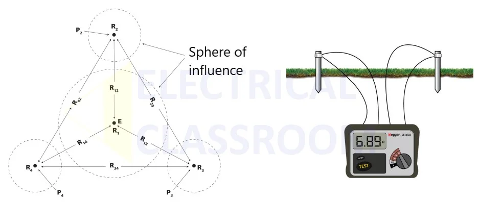
If the sphere of influence of the ground electrode is large that the sphere of influence of the current electrode is so close or the space on the testing ground is limited that acceptable spacing cannot be derived, the star-delta method can be used for earth resistance measurement.
This method is named after the configuration of the test electrodes and the lines of measurement. The test is conducted by inserting three test electrodes of known resistances around the ground electrode to be tested. These probes are placed equidistant from the earth electrode, displaced at an angle of 120 degrees between them, thereby forming an equilateral triangle.
The earth electrode is isolated from the system and a series of resistance measurements are conducted between all test electrodes to the earth electrode and between all pairs of test electrodes. The measured resistance is the sum of the resistances of individual electrodes and the ground.
For example, if the resistance of the ground under test “E” is R1 and that of the test electrodes (P2, P3, and P4) are R2, R3, and R4 respectively, the resistances measured between “E” and each of P2, P3 and P4 will be R1+ R2, R1+ R3, and R1+ R4 respectively.
A total of six resistance measurements are conducted between the electrodes, (R12, R13, R14, R23, R34, and R42), and the earth resistance R1 can be calculated using the following formulae:
1] R1 = 1/3 [(R12 + R13 + R14) – (R23 + R34 + R42)/2]
2] R1 = 1/2 (R12 + R13 – R23)
3] R1 = 1/2 (R12 + R14 – R42)
4] R1 = 1/2 (R13 + R14 – R34)
If the results of equation 1 match that of the other three, then satisfactory conditions existed for measurement. Otherwise, One of the test electrodes has overlapped the sphere of influence of the earth electrode under test. In the case of false measurement, the operator has to redo the tests. Performing the below calculations can help the operator find which electrode has overlapped the sphere of influence.
R2 = 1/2 (R12 + R23 – R13)
R2 = 1/2 (R12 + R42 – R14)
R2 = 1/2 (R23 + R42 – R34)
R3 = 1/2 (R13 + R23 – R12)
R3 = 1/2 (R13 + R34 – R14)
R3 = 1/2 (R23 + R34 – R42)
R4 = 1/2 (R14 + R42 – R12)
R4 = 1/2 (R14 + R34 – R13)
R4 = 1/2 (R42 + R34 – R23)
This method of earth resistance measurement might be time-consuming and involve a lot of calculations. But the result obtained is found to be more accurate than the others earth testing methodologies.
Dead earth method or Two electrode method
The dead earth method or Two electrode method is one of the earth resistance measurement methods adopted whenever there is no room for additional test electrodes. If a metallic water pipe system is available and the water system is extensive, the pipe system can be used to test the earthing resistance of an existing earth electrode. The water system covering a large area would have very less resistance.
The dead earth method can be used only when the water-pipe system is entirely metallic, has negligible resistance and the electrode under test is not far away from the piping system.

The dead earth method for earth resistance measurement must always be the last resort if none of the other earth resistance measurements are possible.
Slope Method
The slope method is suitable for substations and such others large grounding systems. In these systems the distance between the electrodes needs to be significantly large so as to place the test electrodes outside the sphere of influence of the earth electrodes. Also long leads may be necessary to connect the current and potential electrodes.
In such conditions, slope method can be used. This method involves taking numerous resistance measurements between the earth electrode and the potential electrode. The potential test electrode is moved from very close to the ground grid/ earth electrode to the position of the current test electrode.
The resistance measured is plotted on a graph from which the resistance value can be obtained. The image shows such a graph in which it can be be observed that at approximately 60 percent of the distance the slope is quite gentle and the curresponding resistance is the true resistance of the earth grid being measured. In this case it is 20 ohms.
Above are the most commonly used methods of ground resistance measurement in an existing system. It is always important to understand the operation of the measurement instrument before carrying out the measurements.
View and download the earth resistance testing manual from fluke here: https://dam-assets.fluke.com/s3fs-public/1623-2__umeng0000.pdf


I’m grateful 🥰 for letting many know the many possible yet hidden methods of Ground / Earth Resistance Measurement!
Thank you so much 😊!
Your article is detailed and the images have helped drive the ground earth resistance measurement concept home for everybody.