Effective electrical earthing plays an important role in safeguarding people from the risk of electric shock and ensures a low impedance path for electric discharges to pass to the general mass of the earth under both normal and fault conditions. In this article, let’s discuss the various earthing systems as per IEC 60364 and BS 7430. Earthing types for low voltage systems are defined by these standards.
Nomenclature used by IEC 60364
The first letter defines the relationship between the neutral point and the earth/ground.
- T – Earth (from the French word Terre): basically means that neutral is solidly connected to the Earth/ground.
- I – Isolated Earth: Basically means that the neutral and earth are isolated or a high impedance-earthed neutral (e.g. 2 megaohm resistance between the neutral and the earth).
The second letter defines the relationship between the conductive parts of an electrical installation and the earth/ground.
- T – Direct connection between the exposed conductive parts and the earth.
- N – The exposed conductive parts are directly connected to the neutral conductor.
The third and the fourth characters define the nature of the earth and neutral conductors:
- S – Separated earth and neutral conductors.
- C – Combined earth and neutral conductor.
In addition to the above, you may come across the following terms as well:
- PEN – Protective Earthed Neutral conductor.
- PE – Protective Earth conductor.
- PME – Protective multiple earthing.
Types of electrical earthing for low-voltage systems as per IEC 60364 & BS 7430
Different types of earthing systems by IEC 60364 are:
- IT system – Unearthed or impedance-earthed neutral system with a direct connection between the exposed conductive parts and the earth.
- TT system – Directly earthed neutral system with a direct connection between the exposed conductive parts and the earth.
- TN system – Directly earthed neutral system with a direct connection between the exposed conductive parts and the neutral.
IT system
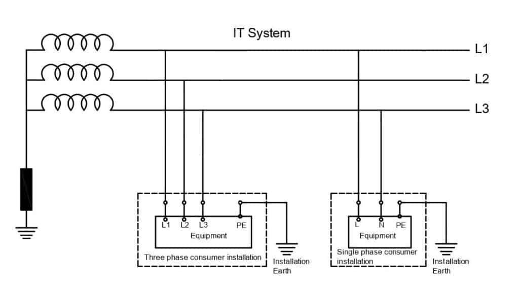
In an IT system or the source neutral can either may not have a direct connection to the earth or can be connected to the earth through a sufficiently high impedance(in the order of 1,000 to 2,000 Ω). All exposed conductive parts, such as the metallic parts of the loads are interconnected and connected to an earth electrode. If the loads are situated far from each other, they can be individually earthed. The local earth electrode does not have any connection to the source earth electrode.
The system can continue to operate without interruptions in spite of the phase-to-earth faults. A separate short circuit protection device or RCD needs to be installed for protection against phase-to-phase faults. It is not advisable to distribute neutral for this system. If neutral is distributed, it shall be no more protected.
In general, an IT system is preferred for locations where the supply has to be maintained in spite of faults, such as medical centers and mobile generators, where the connection with the earth is difficult.
Advantages of an IT system
- Service continuity in spite of phase-to-earth faults.
- Short circuit currents during insulation faults are very low.
Disadvantages of an IT system
- In the event of phase two earth faults, the voltage of the two unaffected phases increases to the value of the phase-to-phase voltage.
- Locating faults in a large network is difficult.
- Overvoltage limiters must be installed.
- IT system requires continuous monitoring.
TT systems
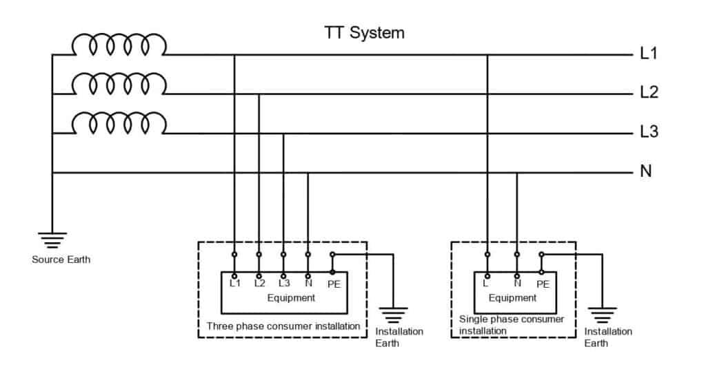
In a TT system, the neutral or midpoint of the source shall be directly connected to the earth and all the exposed conductive parts, such as the metallic parts of the loads are interconnected altogether or in groups and connected to an earth electrode. The local earth electrode does not have a direct connection to the source earth electrode.
The system neutral may or may not be distributed. Residual current or earth fault protection is mandatory for this system. All the exposed conductive parts that are connected to a common earth electrode must be protected by a single protection device. The system design is such that the equipment is isolated upon the occurrence of the first insulation fault.
Advantages of a TT system
- The system design is very simple.
- Easy to locate faults.
- Since the circuit is protected with residual current devices, there is no risk of fire when their sensitivity is below or equal to 500 mA.
- The short circuit currents on the occurrence of insulation failures are small.
TN systems
In a TN system, the neutral is directly earthed and all the exposed conductive parts, such as the metallic parts of the loads are connected to the neutral. No separate earthing is done at the consumer end.
Based on the structure, the system can be further classified as follows:
- TN-C system
- TN-S system
- TN-C-S system
TN-C system
In a TN-C system, the protective earth and the neutral are combined into a single conductor called PEN (Protective Earthed Neutral ) conductor. The PEN conductor is earthed evenly throughout its length to avoid potential rises in the exposed conductive parts if a fault occurs. This type of installation is quite unusual.
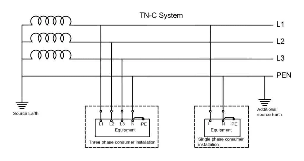
The advantage of the TN-C system is that overcurrent protection devices can be used to ensure protection against indirect
contact.
Disadvantages of TN-C system
- The fault currents are very high and pose the risk of fire.
- Insulation damages may result in the failure of motors.
- It is not advisable for systems with many electronic devices due to the presence of harmonics in the neutral conductor.
- Might require an extra equipotential bonding.
TN-S system
In a TN-S system, the neutral conductor is earthed and all the exposed conductive parts, such as the metallic parts of the loads are connected to the PE conductor. The PE conductor can be the armor and sheath of the underground supply cable. Since the earthing conductor is separate, it provides clean earth.
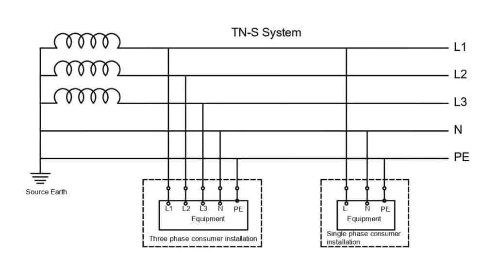
Similar to TN-C, in a TN-S system, overcurrent protection devices can be used to ensure protection against indirect
contact. The biggest disadvantage of a TN-S system is that the consumer installation will be left without earth if the connection to PE becomes an open circuit. If an earth fault happens under this condition, the conductive parts of the consumer installations will be raised to the line voltage. No circuit breakers might operate under this condition.
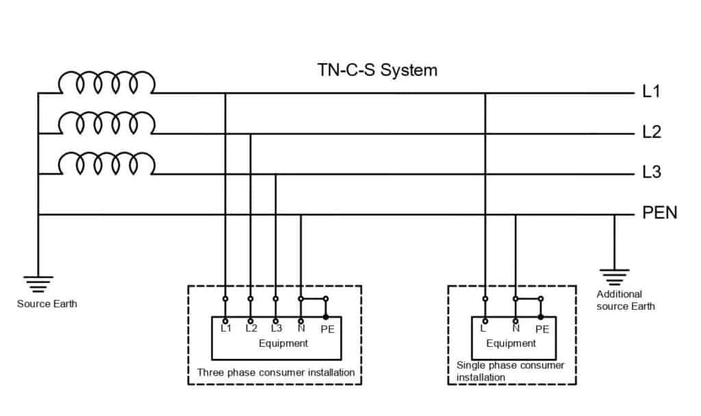
TN-C-S system
In TN-C-S systems, the consumer installations have separate conductors for neutral and the earth as in the case of TN-S, but at the supply, the protective earth and the neutral are combined into a single conductor (PEN conductor) as in TN-C. The PEN conductor is earthed evenly throughout its length to avoid potential rises in the exposed conductive parts if a fault occurs.
TN-C-S system is also known as PME (Protective multiple earthing) systems. The multiple earthing of the PEN conductor ensures that the exposed-conductive parts remain connected to earth always. If the PEN conductor is opened at the source end, the consumer installation will experience unacceptable voltage variations.
The electrical earthing systems mentioned above can be primarily used for low voltage installations. Electrical earthing for medium voltage installations is discussed here: Types of grounding.
Additional reference: IEC 60364–4-41
Dear Sir/Madam,
This is a very good article and explains the different systems expertly.
Is there any information on which of these systems is normally used with larger sized Solar PV systems?
Also, is there anyway to get a copy of this article?
Thanks,
Derek