This article discusses several types of grounding methods. The intention of providing the proper ground is to control the voltage with respect to the ground and provide a low resistance path for the leakage charges to pass to the ground. In addition, the ground is used to detect unwanted connections between the phase and the line and ground (during electric shocks, ground faults, etc.) and trip the circuit breaker to interrupt the current flow to the equipment.
While there are many possible causes for a ground fault, the most frequent are inadequate insulation, physical harm to the insulation system, and severe transient or steady-state voltage loads on the insulation. These issues may be brought on by moisture, contaminating air, deteriorating insulation, mechanical strains, etc. There is always a latent risk of a problem, usually during equipment installation or significant maintenance, even though the previously listed conditions can be prevented by maintaining a good maintenance schedule.
The effects of ground faults could be highly destructive when the grounding scheme is not proper. Destruction could be of any form: arc blast, fire, equipment damage, or electrocution of the person working on the equipment. On the other hand, if a proper grounding scheme is been implemented, the destruction can be limited to a shutdown.
Types of grounding
Depending on how the equipment is grounded, a grounded system can be classified as follows:
- Ungrounded system.
- Solid grounded system.
- Resistance grounded system.
- Low resistance grounding
- High resistance grounding
- Reactance grounded system.
- Resonant grounded system.
Ungrounded system
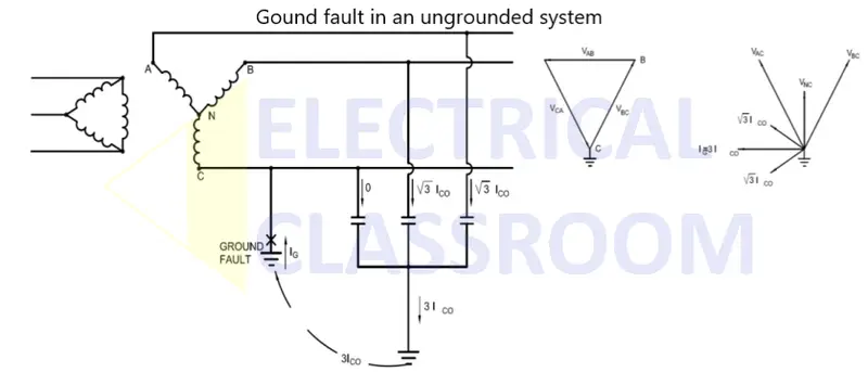
The system in which the neutral of transformers and generators are not grounded is known as an ungrounded system. Even though there is no physical grounding, a capacitive coupling does exist between the line conductors and the ground. Therefore an ungrounded system can also be considered a system grounded by capacitance.

When operating normally, in an ungrounded system the capacitive currents and phase-to-ground voltages are equal and displaced 120 ° C from each other. This makes the system fully balanced.
Let us assume that phase C is in contact with the ground. Under this condition, the current flowing from the other two conductors through the capacitance, to the ground increases by a factor of root 3. And no current flows through the capacitor of phase C.
In an ungrounded system, ground faults result in overvoltages that are 6 to 8 times higher than the nominal voltage. These overvoltages are the result of the inductive reactance of the system and the capacitance between the phases and the ground. They can be highly destructive and can damage insulation systems.
Click here to learn more about ungrounded systems
Solid grounded system
A solid grounded system is one in which the neutral conductor of power transformers, grounding transformers, or alternators is directly connected to the ground. Since the neutral is directly grounded, this system allows connection to line to neutral (Single phase connections). Moreover, ground faults can be detected easily using zero sequence or residual current relays.

The downside of a solidly grounded system is that the ground fault can be so high that it could instantaneously damage the equipment. If the fault is detected and the equipment is isolated at an early stage the damages can be eradicated.
Click here to learn more about solid grounded systems
Resistance grounded system
In this type of grounding, the neutral conductor of power transformers, grounding transformers, or alternators is directly connected to the ground through a resistor. By grounding a system through a resistor, the damages caused to equipment during ground faults can be reduced. This can also limit the momentary voltage drops caused in a system during faults.
There are two types of resistance grounding:
- Low resistance grounding
- High resistance grounding
Low resistance grounding

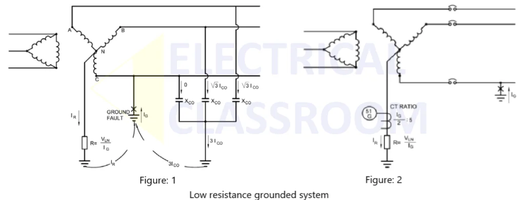
Low resistance grounding is done by connecting the neutral to the ground through a low resistance. The value of resistance used for grounding can be calculated using the following formula:
Where,
- VL is the line to ground voltage.
- IG is the desired current flow to the ground.
At the moment of fault, the fault neutral voltage may rise up to the line voltage and the current begins to flow through the grounding resistor. The ground faults in a low resistance-grounded system can be easily detected using an overcurrent relay (residual current relay 51G). If the measured current exceeds the design values, the relay can open the circuit breaker.
In medium voltage systems of 15 kV and lower, grounding through a low resistance is used, especially when large motors are connected at the load end and when it is desired to reduce ground fault to hundreds rather than thousands of amps.
High resistance grounding
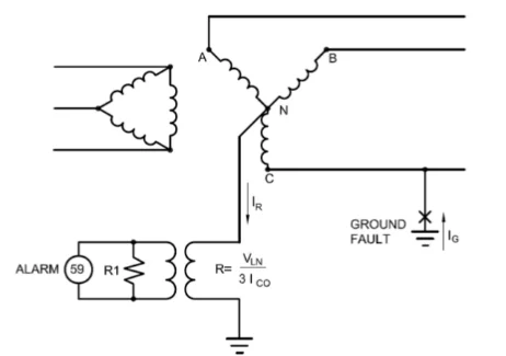
High-resistance grounding is suitable for systems that do not need to be isolated immediately after the occurrence of faults. In high resistance grounding, the neutral is grounded through a high resistance so that the current flow to the ground in the event of a ground fault is typically limited to 10A or less.
A high resistance allows the operation of the system to continue even when a ground fault is present. Under normal conditions, the neutral point of the transformer shall be at the ground potential. In the event of a ground fault, the neutral voltage rises to phase to neutral voltage. An overvoltage relay is used to detect this ground to neutral voltage and generate an alarm on fault detection. A typical high-resistance grounding system is shown in the figure.
The advantages of a high resistance grounded systems are:
- Operation continuity in spite of ground faults.
- There is no need for coordinated ground fault relaying.
- Transient overvoltages due to re-striking are reduced.
High resistance grounding is suitable for low voltage without single phase loads and medium voltage systems where operation continuity is the top priority.
Click here to learn more about resistance grounded systems
Reactance grounded system
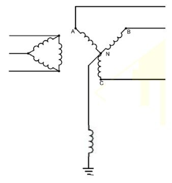
Reactance grounding is achieved by grounding the system through a reactor. Unlike low and high resistance grounding, the ground fault currents in the system of this type shall be higher. Under arcing ground fault situations, this inductive reactance to ground resonates with the system’s shunt capacitance to ground and generates extremely high transient overvoltages on the system.
Click here to learn more about reactance grounded systems
Resonant grounded system
A resonant grounded system is a system grounded through a variable impedance reactance. A variable impedance reactance is connected between the transformer neutral and the ground. This reactor compensates for the line-to-ground capacitance such that the zero-sequence network becomes a very high impedance path. In a resonant grounded system, most of the ground faults can be cleared without circuit breaker tripping. This can be applied to high voltage transmission and generation stations.
Click here to learn more about resonant grounded systems
Comparison of different types of grounding systems
| Ground fault current (% of 3phase fault current) | Transient overvoltages | Surge Arresters | Remarks | |
|---|---|---|---|---|
| Ungrounded system | Below 1% | Very high | Ungrounded neutral type. | Not recommended due to overvoltage. |
| Solid grounding | Could be 100% or even higher | Not Excessive | Grounded neutral type. | Used for systems over 15kV and below 600V. |
| Low resistance grounding | 20% and downwards to 100A to 1000A | Not Excessive | Ungrounded neutral type. | Generally used for 2.4kV to 15kV systems with motor loads. |
| High resistance grounding | Below 1% | Not Excessive | Ungrounded neutral type. | Used for systems below 600V where operation continuity is the priority. |
| Low reactance grounding | Between 25% and 100% | Not Excessive | Grounded neutral if the current exceeds 60%. | Used for systems over 15kV and below 600V. |
| High reactance grounding | Between 5% and 25% | Not Excessive | Ungrounded neutral type. | Not recommended due to overvoltage. |
| Resonant grounding | Close to zero. | Not Excessive | Ungrounded neutral type. | Best suited for all medium voltage and commercial applications. |
Read more: Types of Electrical Earthing as per IEC 60364 & BS 7430


