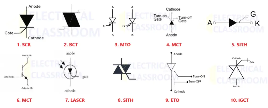
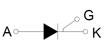
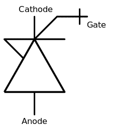
Thyristors are high-speed semiconductor switching devices that are made up of four layers of alternating p and n-type materials. They are used in AC/DC switching and AC power control applications. The thyristor symbol is a diode symbol that has three terminals, the gate, anode, and cathode.
- Silicon Controlled Rectifier (SCR)
- Bidirectional Control Thyristor (BCT)
- Gate Turn off Thyristor (GTO)
- MOS Turn-off Thyristor (MTO)
- MOS Controlled Thyristor (MCT)
- Light Activated Silicon – Controlled Rectifier (LASCR)
- Static Induction Thyristor (SITH)
- TRIAC
- Emitter Turn-off Thyristor (ETO)
- Integrated Gate Commutated Thyristor (IGCT)
- Gate Assisted Turn off Thyristor (GATT)
- Comparison of different thyristors
Silicon Controlled Rectifier (SCR)
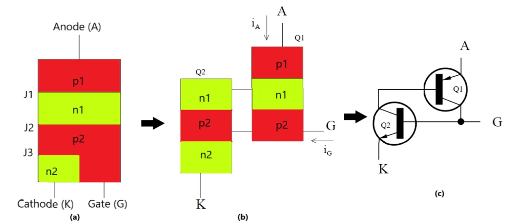
Silicon Controlled Rectifier (SCR) is one of the most commonly used thyristors. They are high-speed semiconductor switching devices. They are similar to Shockley diodes but with an extra terminal. The chosen material for construction for the SCR is silicon. SCR works like a silicon rectifier diode with an anode and a cathode.
The anode is the positive terminal and the cathode is the negative terminal of the SCR. It has four layers of alternating P and N type material. It also has an additional control terminal called the gate. The presence of the gate allows the SCR to be triggered into conduction. It is a unidirectional device that allows the current to only flow when in one direction and opposes the flow in the opposite direction.
The SCR can be switched on by either an exceeding forward break over voltage or gate current. The gate current controls the amount of forward break over voltage required to switch the SCR ON.
A trigger voltage/pulse is applied to the gate terminal when the anode and cathode are forward biased. This switches the SCR into a “conducting” state. The current then flows between the anode and cathode. Once the SCR is conducting the trigger current will continue to flow even if the gate terminal is removed. When the anode and cathode are in reverse bias the SCR will not conduct even if a trigger pulse is applied at the gate terminal.
Read More: Silicon Controlled Rectifier (SCR) in detail
Bidirectional Control Thyristor (BCT)
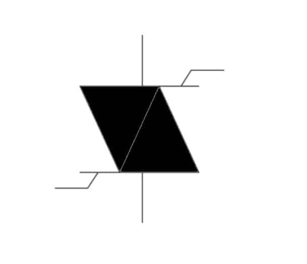
The bidirectional control thyristor makes use of two SCR thyristors which are configured in an anti-parallel arrangement forming a single device. As it can be observed from the structure, it has two separate gate terminals for each of the thyristors. One gate terminal switches the current on in the forward direction while the second gate terminal switches the current on in the opposite direction.
The two thyristors function independently of one another. One major challenge faced in the construction of BCT was the cross-talk between both the transistors. Therefore, a photomask has been set up to prevent the effects of the harmful cross talk when the BCT is under operation.
Gate Turn off Thyristor (GTO)
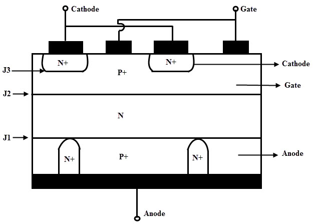
The gate turn-off thyristor is a type of thyristor that can turn on and turn off the main current with the help of a gate drive circuit. The GTO comprises two layers of P-type material and two layers of N-type material in a PNPN format. They are used in high current and high-speed switching applications which include chopper circuits and inverters.
In this type of thyristor, the n+ layer at the cathode end is heavily doped. This increases the emitter efficiency resulting in a low breakdown voltage at junction 3. To maintain the high emitter efficiency the doping level at the p-type gate is low. The junction between the P+ anode and the N base is also known as the anode junction.
For the GTO to remain in an “ON” state the P+ anode region must be heavily doped. This ensures a higher efficiency at the anode junction. It turns on when a positive voltage is applied at the gate terminal. It can also be turned off when a negative voltage is applied at the gate terminal. The device does not latch and requires at least 1% trigger voltage to remain in a conduction state.
However, when the GTO has a heavily doped P anode region then the turn “OFF” capabilities are compromised. For the thyristor to have good turn OFF properties the doping of the P+ gate region and the N+ layer between the anode needs to be heavily doped.
MOS Turn-off Thyristor (MTO)
In order to overcome the limitations of a GTO, Silicon Power Company developed MOS Turn-off Thyristor or MTO by combining GTO and a MOSFET. The MTO provides the same functionality as the GTO but needs only a signal level voltage to turn itself on and off. Also, the structure of the MCT is almost similar to that of GTOs.
MOS Controlled Thyristor (MCT)
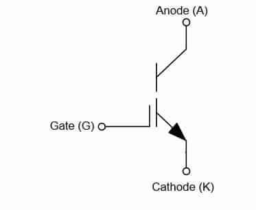
The MOS controlled thyristor is a semiconductor device that combines the current and voltage of the thyristor with the MOS gate turn-on or off. It is a high frequency, low conduction drop and high power device which is used for medium and high power applications.
The structure has three junctions the anode, cathode and gate. The PNPN layers are sandwiched between the anode and cathode. The thyristor is switched on when a negative trigger voltage is applied at the gate with regard to the anode. It would be switched off when a positive trigger voltage is applied at the gate with respect to the anode. It is suitable for applications such as motor drives, static VAR compensators, uninterrupted power supplies, etc.
Light Activated Silicon – Controlled Rectifier (LASCR)
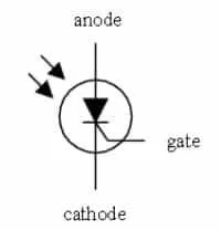
LASCR is a type of SCR which is triggered using a light source such as the LED. It consists of three terminals the cathode, anode, and gate. A trigger current is initiated through a light source when the photon particles hit the junction to produce electron-hole pairs. This trigger current is supplied to the LASCR which activates the gate terminal and hence current flows through the device. This also aids in the prevention of electrical noise disturbances from being generated. The power circuit and the light source circuit are electrically isolated by the LASCR.
The thyristor is made up of silicon. The glass lens in the LASCR focuses the light from the light source on the semiconductor device. A silicon pellet is situated at the bottom of the thyristor device. The device goes into a conduction state when light intensity dislodges the electrons in the semiconductor crystal.
Static Induction Thyristor (SITH)
The static induction thyristor is also known as the field-controlled diode. It allows the conduction of large currents which have a low forward voltage and turn-off quickly. It is a high-frequency power semiconductor device.
The device is in an “ON” state if the anode is positive and the gate voltage is 0. This makes the device behave like a diode where the current is allowed to flow free from any obstructions. When the P+N junction is forward biased, holes are injected into the N– region which restricts the conductivity of the device. A depletion layer blocks the anode current when the gate is in reverse bias with respect to the cathode. This switches the device OFF.
TRIAC
The TRIAC is a three-terminal thyristor that can conduct current in both directions when activated properly which is used in AC switching applications. In a TRIAC two SCR thyristors are connected parallel and in opposite direction with one another with a common gate terminal. This allows it to conduct current in both directions when a trigger voltage is applied.
Emitter Turn-off Thyristor (ETO)
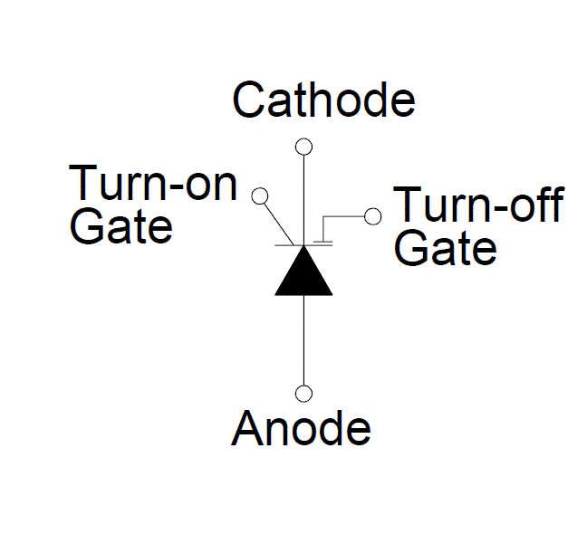
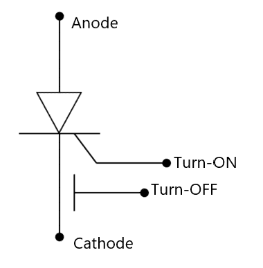
This type of thyristor is a hybrid MOS-bipolar high power semiconductor device that consists of the two N MOSFET and two P MOSFET and GTO’s high voltage and current features. The N MOS is connected in series to the cathode terminal and the P MOS is connected between the cathode and gate terminal of the device. It can be observed from the figure that it has two gate terminals.
One gate terminal turns on the device and the other switches off the device. A positive voltage gate voltage at both gates switches N-MOS on and P-MOS off, therefore, turning the device ON. It can be switched OFF by providing a negative gate voltage at the N-MOS gate. This allows the residual carrier to flow through the P-MOS which allows fast switching to take place between the two states.
Integrated Gate Commutated Thyristor (IGCT)
The IGCT is a gate-controlled turn-off switch that has similar properties to a transistor. Its conduction process is like the thyristor but it turns off like a transistor. The conduction losses for this type of thyristor are also very low.
The structure of the IGCT comprises a gate commutated thyristor (GCT). It has a multi-layer PCB which drives the circuity. The GCT is a switching device that makes use of a fast and large current pulse to drain the current from the GCT cathode. This ensures “fast turn-off”. For conduction of reactive load, an integrated diode is present in the GCT. To switch on the IGCT a gate current needs to be provided.
Gate Assisted Turn off Thyristor (GATT)
This type of thyristor is used in electronics that require a fast turn-off. A negative gate voltage is applied to assist the turn “OFF” process. This also reduces the anode to cathode voltage. When a reverse gate voltage is applied the minority carriers accumulated on the n-type base region are drained. This ensures that the gate to cathode junction is not forward biased hence speeding up the turn-off process.
Comparison of different thyristors
| Type | Gate Control | Switching frequency | Maximum voltage rating |
|---|---|---|---|
| SCR | Current for turn-on and no turn-off control | Typically 60Hz | 1.5kV |
| BCT | Current for turn-on and turn-off | Typically 60Hz | 6.5kV |
| GTO | Current for turn-on and turn-off | Typically 5 kHz | 4.5kV |
| MTO | Current pulse for turn-on and voltage pulse for turn-off | Typically 5 kHz | 10kV |
| MCT | Two gates, one for turn-on and one for turn-off | Typically 5 kHz | 4.5kV |
| LASCR | Light signal for turn-on and no turn-off control | Typically 60Hz | 6.5kV |
| SITH | Two gates, one for turn-on and one for turn-off | Typically 100 kHz | 2.5kV |
| TRIAC | Current for turn-on and no turn-off control | Typically 60Hz | 1.2kV |
| ETO | Two gates, one for turn-on and one for turn-off | Typically 5 kHz | 4.5kV |
| IGCT | Two gates, one for turn-on and one for turn-off | Typically 5 kHz | 5kV |




Sending me Hindi