A Silicon Controlled Rectifier (SCR) is a unidirectional semiconductor device that can be triggered into conduction by applying a positive gate current. It led to tremendous advancements in power semiconductor devices. They are also known as phase-control thyristors. They are high-speed semiconductor switching devices, similar to Shockley diodes but with an extra terminal. They generally operate at the line frequency (50/60 Hz), turned ON by gating trigger pulse, and turned off by natural commutation.
Symbol of Silicon controlled rectifier
The above figure shows the symbol of an SCR. It works like a silicon rectifier diode with an anode and a cathode. The anode is the positive terminal and the cathode is the negative terminal. It has four layers of alternating P and N-type material. It also has an additional control terminal called the gate. The presence of the gate allows the SCR to be triggered into conduction when it is in forward conduction mode. It is a unidirectional device that allows the current to only flow when in one direction and opposes the flow in the opposite direction.
The SCR can be switched on by either an exceeding forward break-over voltage or gate current. The gate current controls the amount of forward break-over voltage required to switch it ON. A trigger voltage/pulse is applied to the gate terminal when the anode and cathode are forward-biased. This switches it into a “conducting” state. The current then flows between the anode and cathode. Once it starts conducting the trigger current will continue to flow even if the gate terminal is removed. When the anode and cathode are in reverse bias the SCR will not conduct even if a trigger pulse is applied at the gate terminal.
To switch the SCR off the current flowing through the anode to the cathode needs to be reduced to a critical holding current value which is near zero.
Two Transistor Model of SCR and its working principle
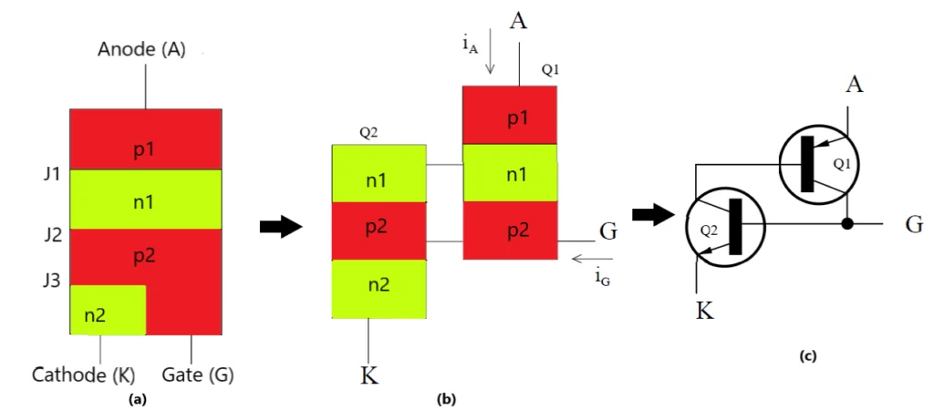
Theoretically, the four layers of the SCR are taken as a small circuit that consists of two transistors, PNP and NPN. This can be seen in figure 2. In figure 2(b) it can be observed that P2 forms the emitter of Q1 and base of Q2. N1 forms the base of Q1 and the collector for Q2.
So, the collector current of the NPN transistor (Q2) flows directly into the base of the PNP transistor (Q1) and the collector current for Q1 flows directly into the base of Q2. These transistors rely on one another for the conduction of current in the thyristor. This is because each of the transistors gets its base-emitter current through the other’s collector-emitter current. Therefore, even if an anode-to-cathode voltage is present, it is essential to provide a base current to start the conduction process. Hence, a trigger voltage needs to be applied at the gate terminal.
The gate terminal, which is the base of Q2 can be made positive with respect to the cathode which is the emitter of Q2 by the application of a gate pulse (trigger voltage). This would allow a small current or large current to be injected into the Q2 base. The NPN transistor would be switched ON and the voltage across the Q2 collector would fall. This will result in current flowing into the Q1 (PNP) transistor, therefore, causing a rapid rise in the Q1 collector and Q2 base voltage.
The Q2 base-emitter junction will become more forward-biased which would switch on Q1. This would result in both the transistors remaining operating even if the gating pulse is removed. A large current is observed to be flowing through the P1 anode (A) and N2 cathode (K). The resistance between the anode and cathode falls to zero and only a load current in the SCR circuit can now limit the flow of current. Each transistor collector is now supplying a large current to the base of the other transistor.
If no trigger voltage is applied at the gate (G), then the potential at the cathode (K) would be the same as the gate (G). So, even if any voltage is applied between the anode (A) and the cathode (K) which is less than the forward break-over voltage, no current will flow through the SCR. The anode would be positive with respect to the cathode. This would result in the two outer P-N junctions being forward-biased, but the center N-P junction is reverse-biased.
Hence, the Q2 transistor has no voltage being applied between the base and the emitter terminals and therefore these terminals will not be conducting. Since the collector voltage of Q2 (NPN) provides the base voltage drive for Q1 (PNP), the base-emitter junction will be reverse biased which would cause both the transistors to be switched off and no current would flow through this small SCR circuit between the anode and the cathode. The SCR in this state would be operating in its forward-blocking region. As a result, the SCR is in a turn-off condition.
When the anode terminal of the thyristor is negative with respect to the cathode, the center base-emitter (N-P) junction would become forward biased, the two outer P-N junctions will be reverse biased. Therefore, the thyristor would behave like a diode blocking the flow of reverse current until a high voltage, beyond the breakdown voltage of the two outer junctions is applied. This would allow the thyristor to go into a conduction state even without the application of a gate trigger voltage.
Commutation techniques
The SCR can be forced out of conduction in two ways:
Anode Current interruption
Anode current interruption can be done by breaking the anode current path by either providing a path around the SCR or by dropping the anode voltage to such a point that the anode current is less than the holding current.
Forced Commutation
This method makes use of external circuits which would force the current to flow in the opposite direction. The circuit consists of a capacitor and a switch. When the SCR is in an ON state the switch is open and the capacitor (CC) is charged to the supply voltage through resistor Rc. To switch it off, the switch is first closed so that the capacitor is placed across the SCR. This forces the current flowing through the SCR to flow in the opposite direction to the forward current. Forced commutation is commonly used in AC circuits where the SCR turns off when the AC reverses.
Operation Modes of the SCR
Forward Blocking Mode:
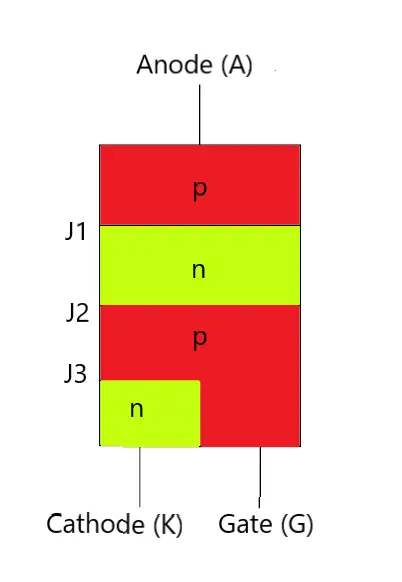
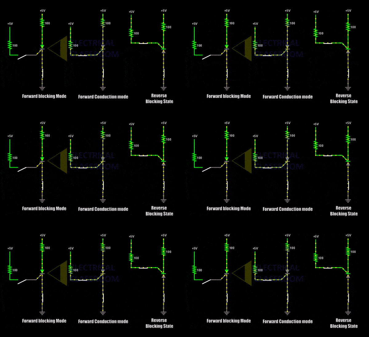
When the anode voltage is made positive with respect to the cathode and no gate pulse is applied, the junctions J1 and J3 are forward-biased and J2 is reverse-biased. The SCR stays in the off-state or forward-blocking mode.
Forward conduction Mode:
In a forward-biased SCR and if a gate current is injected by applying positive gate voltage between the gate and cathode terminals, it turns ON and it enters forward conduction mode.
Reverse Blocking Mode:
In this operating mode, a positive voltage is applied at the cathode and a negative voltage is applied at the anode. No trigger voltage is applied at the gate, therefore keeping it as an open circuit. The junctions J1 and J3 in figure 1 are reverse-biased. As a result, no current would flow in this operating mode.
Characteristics of a Silicon-Controlled Rectifier
Forward- break over voltage (VBR):
This is the voltage at which the silicon-controlled rectifier enters the forward conduction region. The forward conduction region is the only region in which the thyristor is triggered into its conduction state.
Latching Current (IL):
Latching current is the minimum current required to maintain the SCR in the on-state immediately after it is turned ON and the gate trigger is removed.
Holding Current (IH):
The value of the forward anode current below which the SCR switches from the forward conduction region to the forward blocking region is called the holding current. This is the minimum amount of current required to hold the SCR in the “ON” state. It will continue to conduct until the forward current (anode current) drops below the holding current. Holding current ranges from 1 milliamp to 50 milliamps depending on the type of application.
Off-state Current (ID):
In forward blocking mode, a negligible amount of leakage current flows through the SCR. This current is known as off-state current.
Reverse Current (IR):
In reverse blocking mode, a negligible amount of leakage current flows through the SCR. This current is known as reverse current.
Gate Trigger Current:
When the SCR is operating in the forward blocking region, it does not conduct. This is because even though junctions J1 and J3 are forward-biased due to the positive voltage applied at the anode and the negative voltage applied at the cathode, the junction J2 becomes reverse-biased which poses an obstacle and prevents the forward current from flowing.
For the current to flow it is important to apply a reverse voltage that is greater than the breakdown voltage of the SCR so that Avalanche breakdown can occur. Only then it can go from the forward blocking operation mode to forward conduction operation mode. The gate trigger current is the maximum current required to switch it from the forward blocking region to the forward conduction region under specific conditions.
Applications of the SCR
In addition to cost-effectiveness, ruggedness, low conduction losses, and high efficiency, silicon-controlled rectifiers have high voltage and high current capabilities. These properties make them suitable for dc-ac converters applications. They are one of the key components in HVDC transmission systems.
The ON-state voltage of an SCR ranges between 1.2 V to 2.5 V. It has an operating voltage ranging between 600V and 5000V and an operating current up to 5500A. The switching time of a typical SCR is 100μs and an upper frequency of 60Hz. Below are a few applications of SCRs.
- They are widely used in the switching of electric motors, lamp dimmers, and electric dimmers.
- They are used in HVDC rectification circuits.
- They were used in motor speed control circuits before the invention of IGBT.
- They are used to switch between the raw power source and inverter circuit in a UPS during power failures.
- They are used in battery charging circuits.
- They are used as an alternative to electromechanical relays.
- They are used in soft starters to maintain starting current of induction motors under predefined limits.
- They find application in lighting control circuits.
- They are also used in conjunction with RC circuits to produce repetitive Sawtooth waveforms for Sawtooth generators.
- They are used in overvoltage protection circuits.
Review:
- An SCR is a 4-layer semiconductor device.
- Three terminals of an SCR: Anode, Gate, and Cathode. The device can be triggered into conduction using the gate terminal.
- It latches to conduction mode when its anode is positive with respect to the cathode and a positive gate pulse is applied.
- It enters blocking mode as soon as the forward-biased current is reduced below its holding current.
- It cannot be turned off by a negative gate pulse.


