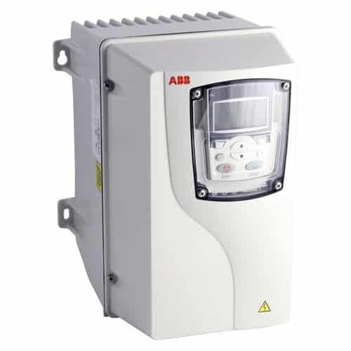
Commissioning of variable speed drive is the process of checking, inspecting, testing, and configuring the equipment at the project site so that it shall fulfill the technical and functional requirements of the customer. This makes the equipment ready for safe operation. This article explains the Commissioning procedure for VFD.
Why is commissioning of variable frequency drive/ variable speed drive important?

Commissioning of variable speed drive is done for the following reasons:
- To ensure that the equipment and the associated field devices have fulfilled all the safety aspects (IEC 60364).
- To ensure that the proper cable selection, installation and termination is done.
- To ensure that the variable speed drive and the motor is properly grounded.
- To ensure that the equipment is functional and meets the contractual norms or customer requirement.
Documents and Instrumentation required while VFD/ VSD commissioning
Before starting the commissioning process, the commissioning engineer has to study the application and the customer requirement. Make sure that the following documents and instruments are ready before the start of the commissioning process.
- Wiring diagram.
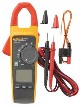
- Clamp meter.
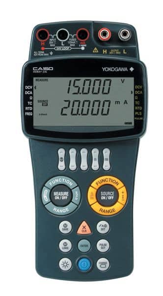
- Handy Calibrator (If required).
- FAT report (If required).
- Motor nameplate details (Rated voltage, full load current, and rated RPM).
- Field instrument details (such as pressure transmitter, pressure switch, flow transmitter, pulse encoder etc.).
- Safety clearance from the site safety officer.
- User manual of VSD.
Once you have the above documents and instruments, you are ready to begin the commissioning process.
Pre-commissioning checklist
Before starting the commissioning process, the following points should be checked.
- Make sure that the voltage rating of the motor matches the drive specification.
- Make sure that the variable speed drive is properly sized to run the motor.
- Make sure that the variable speed drive is properly mounted in the panel.
- Check whether the panel and VSD are properly grounded.
- Make sure that the cables connecting the
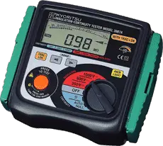
drive inputs and the cables to the motor are properly sized. - Megger the cables connecting the motor and the drive after disconnecting it from either side and ensure the cable is damage free.
- Ensure the input power cable to the drive and cable to the motor are properly installed and terminated.
- Check the cable termination and connection at the motor terminal box.
- Verify whether the control wiring is done properly, as per the wiring diagram.
- Check the field instrument connections.
- Check whether the cable shields are properly grounded.
- In case if the drive is controlled from PLC/PAC or DCS, check the communication cables connections.
- Check the motor for rotor jam.
- Check whether proper cooling arrangements are provided for
drive . - Check whether suitable circuit breaker/ Semiconductor fuse protection is provided for the VFD.
- Check whether the input and output line chokes/ harmonic filter are provided (only if shown in the wiring diagram).
- Check whether Dynamic braking resistance, brake chopper and DC link choke are provided (only if shown in the wiring diagram).
- Note down the rated voltage, full load current, and rated RPM of the motor.
- If more than multiple motors are driven by the VSD at a time, check whether the overload protection circuits are set up between the drive output and the motor terminals.
- Check the proper working of
mechanical brakes, if provided.
Commissioning procedure for VFD/VSD
Once the pre-commissioning checks are completed and all system is found OK, the VSD is ready to be commissioned. Commissioning of the drive includes the following steps.
Check the input supply voltage.
Before starting up the VSD, check the supply voltage at the input side of the circuit breaker terminals. If the supply voltage is within the rated input supply voltage range of the VSD, switch on the circuit breaker. Check the DC bus voltage at the DC bus terminals of the drive. Also, ensure the proper functioning of the cooling fan.
Set all other control and communication parameters.
Most of the variable speed drives available in the market are delivered with application-based pre-set parameters. In spite of that, the following parameters have to be set irrespective of the application.
Minimum output frequency
The minimum output frequency is the lower limit for frequency (i.e.) the output frequency of the VSD cannot be varied below the highest output frequency.
Maximum output frequency
The maximum output frequency is the higher limit for frequency (i.e.) the output frequency of the VSD cannot be varied above the maximum output frequency.
Maximum output Current
Maximum output current is the upper limit for output current. During normal operation, if the output current of VFD exceeds the set limit, the drive will trip on an over-current fault. The current may exceed the upper limit during the start.
Acceleration time.
Acceleration time is the time taken to ramp up the motor to its maximum speed. It depends on load inertia and varies from one application to another.
Deceleration time
Deceleration time is the time taken to ramp down the motor from its maximum speed to zero. . It depends on load inertia and varies from one application to another.
| Application | Acceleration Time | Deceleration time |
| Pump motor | 1.5sec | 1.5sec |
| Conveyors | 3 sec | 3 sec |
| Compressors | 5 sec | 5 sec |
| Hoists | 3 sec | 3 sec |
| Exhaust fans | 60 – 120 sec | 60 – 120 sec |
In addition to the above parameters, few other parameters such as digital input and digital output terminals, analog input and analog output terminals, field communication, pulse inputs, and pulse encoder inputs parameters have to be configured as per the application requirement. Also, some VSD requires protection parameters to be configured.
Advanced features such as brake control, torque boost functions, PID control; droop control, etc. needs to be configured for some application.
Conduct Auto-tuning/ ID-run of VSD.
Auto-tuning is the process by which a variable speed drives measures the impedance of motor winding and determines the VI curve of the motor at different speeds. It is required to input the noted motor rated voltage, rated current, rated frequency, and rated speed before starting auto-tuning. Auto tuning can be stationary or rotational. In the case of rotational auto-tuning, it is advised to decouple the motor from the load/ gear-box. Auto-tuning of a variable speed drive usually takes 60-120 seconds to complete.
If the VSD is used to run more than one motor at a time, auto-tuning of the same is not required. Also, the rated current entered should be the sum of rated currents of all the motors run at a time.
Check the direction of rotation of motor
After auto-tuning the motor, the direction of rotation needs to be checked. The speed reference to the drive is set to 3Hz or 100RPM and the variable speed drive is started manually. If the motor rotates in the reverse direction, the direction of the motor has to be changed by interchanging any two line leads at the motor side. Motor direction can also be changed by programming the drive.
Testing
Once the drive is properly programmed and autotuned, it has to be tested for proper functioning at various output speeds or as per the application requirements.
- Check whether the motor rotates in proper direction.
- Motor should rotate smoothly without hunting, abnormal noise or oscillation.
- Check the operation of the Variable speed drive as per the application requirement.
- Verify the input speed reference and the VSD output.
- Verify whether the motor accelerates and decelerates smoothly.
- Verify and note down the current at no load and full load at various speed references.
- Verify the analogue feedback from the VSD (if required.)
Post – Commissioning of VSD/VFD
After the successful commissioning of variable speed drive, make a clear report of the works done. Also maintain a record of set parameters and current readings noted while testing at no-load as well as at full load, at various speeds.


