One of the key elements affecting ground resistance is soil resistivity. Soil resistivity measurements are conducted before setting up an earthing system, in order to ensure an effective earthing.
Good soil models are the basis of all grounding designs and they are developed from accurate soil resistivity testing. The ground/earth resistance measurements are conducted to ensure that the earth connections are effective and the resistance to the ground fault currents is well within the acceptable limits.
Soil or earth resistivity
It is the most important factor that is to be considered during the design of an earthing system. It is the measure of resistivity offered by the soil to the flow of electric current. The unit of resistivity is Ohm-meter (Ω-m).
The soil resistivity can be calculated using the following formula:
Where A and R are the distance between the electrodes in centimeters and the resistance measured between them in ohms.
Soil resistivity measurement techniques
The two primary methods of measurement are:
- 4-point soil resistivity test using Wenner’s method.
- 4-point soil resistivity test using Schlumberger’s method.
4-point soil resistivity test using Wenner’s method
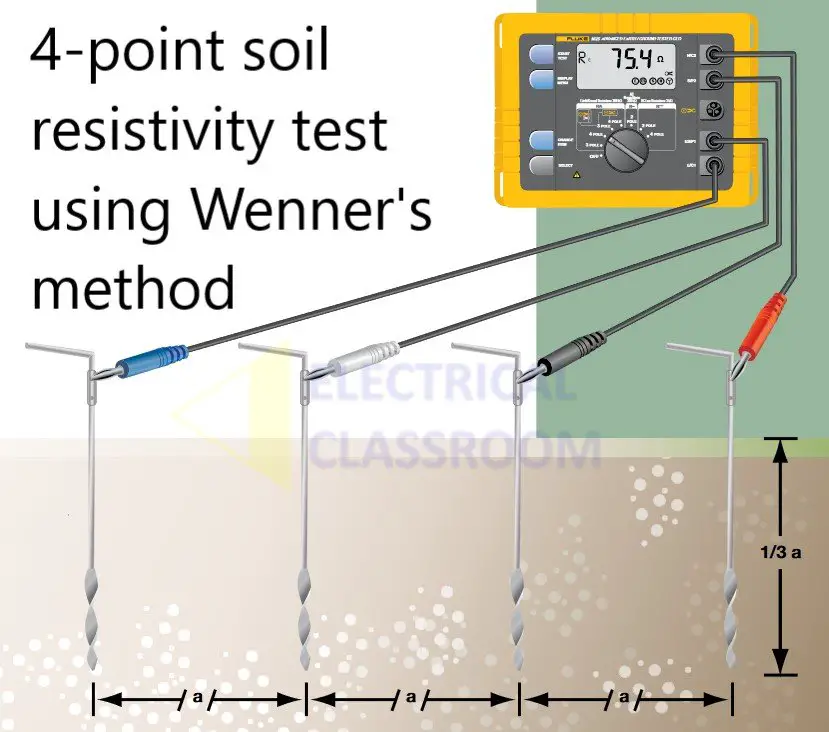
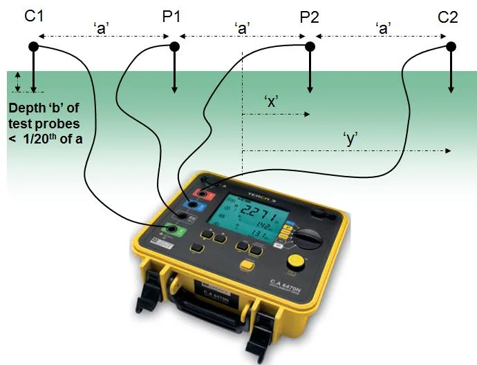
Wenner’s method was developed by Dr. Frank Wenner of the US Bureau of Standards in 1915. In this method, four holes are drilled in the ground at approximately equal depths and equally apart from each other at a distance ‘a’. The distance ‘a’ should be at least three times the depth of the holes. The diameter of the holes should not be greater than 10 percent of the distance between them. Electrodes are placed in these holes, that make contact with the earth only near the bottom.
The resistance between these electrodes is measured using a conventional ohmmeter or a modern earth-ground tester. From the measured resistance the soil resistivity can be calculated using the following formula:
Where a and R are the distance between the eletrodes in centimeters and the resistance measured between them in ohms.
The typical spacing between the electrodes is varied will be 1, 1.5, 2, 3, 4.5, 7, 10 ft, etc. Each spacing is increased at a rate of 1.5 ft. The maximum spacing between the electrodes can be 1 to 3 times the maximum diagonal dimension of the grounding system being designed.
The probe spaced at a distance of 5ft can measure the resistivity of the soil 5ft in depth. The same is true with the electrodes placed at a distance of 40ft. You can weigh the average
soil resistance down to 40 ft in depth and all points in between.
Steps to conduct Werner’s test
- Four electrodes are inserted into the earth at an equal distance, to a depth of one-third of their distance.
- The outer electrodes are called current electrodes(C1 and C2) and the inner probes are called potential electrodes (P1 and P2).
- You can use an earth resistance tester to measure the soil resistance. Connect the measurement probes to the electrodes and to the measurement and read the resistance values.
- Continue measuring the soil resistivity by moving the electrodes far appart from C1 at an equal distance and inserting the probes deeper.
- Note down the resistances at difference distances and depths and calculated the resistivity using the following formula.
Where a and R are the distance between the eletrodes in centimeters and the resistance measured between them in ohms.
Example
If the electrodes inserted to the ground were spaced at a distance of 3 meters and the Earth Ground Resistance Tester reads a value of 100Ω, then the soil resistivity measurement can be calculated as follows:
Schlumberger‘s method
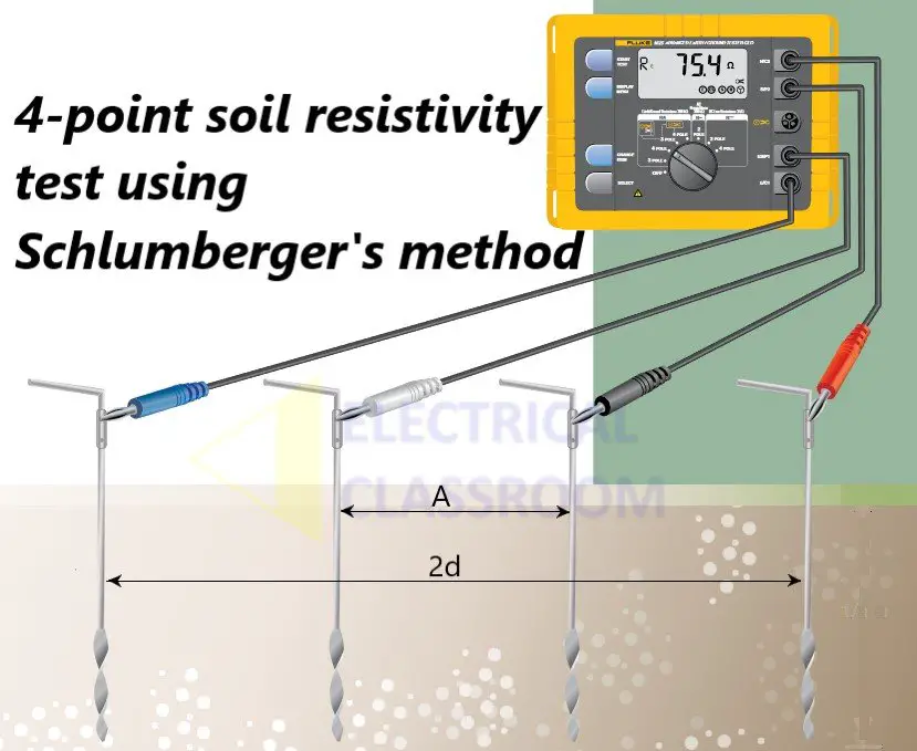
The principle of Werner’s method and Schlumberger’s method is the same. The only difference is the distance between the electrodes. The distance between the electrodes need not be equal. If A is the distance between the inner electrodes and 2d is the distance between the outer electrodes, the resistivity of the soil can be calculated as follows:
Where a and R are the distance between the eletrodes in centimeters and the resistance measured between them in ohms.
The resistivity of various soil types
| Soil types or types of earth | Average resistivity in Ω-m |
|---|---|
| Bentonite | 2 to 10 |
| Clay | 2 to 100 |
| Wet organic soils | 10 to 100 |
| Moist organic soils | 100 to 1,000 |
| Dry organic soils | 1,000 |
| Sand and gravel | 50 to 1,000 |
| Surface limestone | 100 to 10,000 |
| Limestone | 5 to 4,000 |
| Shale’s | 5 to 100 |
| Sandstone | 20 to 2,000 |
| Granites, basalts, etc. 1,000 | 1,000 |
| Decomposed gneisses | 50 to 500 |
| Slates, etc. | 10 to 100 |
| Sea water | 0.1 to 10 |
Soil resistivity measurement location
The following points must be taken into consideration while conducting soil resistivity measurements:
- The tests must be conducted as close to the proposed grounding system as possible.
- When there is no sufficient space to conduct the test, one should consider using the closest open field with similar soil type and conditions to conduct the test.
Electrical interferances could cause unwanted noise in the measurement. Also, metal objects short cutting the electrical paths between the electrodes may cause errorous readings.
Earth resistance measurements on existing systems
The methods discussed above are used for determining soil resistivity when installing a new earth electrode. Those techniques are used to position the electrodes based on soil resistivity. For existing earth electrodes, it is required to test the resistance periodically to ensure proper earthing. This ensures that the resistance to the ground has not increased over time. Depending on the type of installation, various methods are adopted.
References:
“A method of measuring earth resistivity.” [Online]. Available: https://nvlpubs.nist.gov/nistpubs/bulletin/12/nbsbulletinv12n4p469_A2b.pdf.


