The voltage division rule is one of the basic rules of circuit analysis. It is applicable to all series and combination resistor circuits. A series connection of resistors always acts as a voltage divider. In a series connection, the same current flows through each resistor. Hence the voltage drops across each of them are proportional to their ohmic value. Also, the current flowing through them shall be proportional to the total resistance offered by the circuit.
The voltage across each resistor, by ohm’s law, is the current flowing through the circuit multiplied by the value of resistance. Consider a circuit with an ‘n’ number of resistors connected in series and with a voltage V applied across it.
The total resistance offered by this series connection of resistors to the flow of current will be equal to the sum of individual resistances.
Req = R1 + R2 + R3 + ………… + Rn
The total current flowing through the resistor shall be:
I = V / Req ————————————— (i)
The voltage across each resistor R1 shall be
V1 = I.R1 —————————- (ii)
The voltage across each resistor R1 shall be
V2 = I.R2 —————————- (iii)
The voltage across each resistor R1 shall be
V3 = I.R3 —————————- (iv)
The voltage across each resistor R1 shall be
Vn = I.Rn —————————- (v)
Comparing (i) and (ii),
V1 = V.R1/Req
Comparing (i) and (iii),
V2 = V.R2/Req
Comparing (i) and (iv),
V3 = V.R3/Req
Comparing (i) and (v),
Vn = V.Rn/Req
Where Vn is the voltage across the nth resistor.In general,
The voltage across any resistor in a series connection of resistors shall be equal to the ratio of the ohmic value of the resistor divided by the equivalent resistance of the circuit. This is called the Voltage division rule.
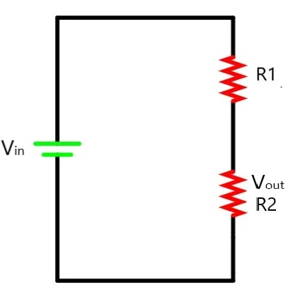
For a better idea, let us consider a circuit with two resistors R1 and R2 connected in series with voltage V applied across it.
Total resistance = R1+ R2
Let the total current be I.
Voltage V = I.(R1 +R2)
Current I = V/(R1 + R2)
Voltage across R1, V1 = I.R1 = V.R1 / (R1+R2)
Voltage across R2, V2 = I.R2 = V.R2 / (R1+R2)
Examples
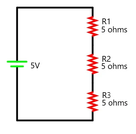
1. Find the voltage across the resistor R3 in the circuit.

Total resistance Rt = 5 + 5 + 5 = 15 ohm
Voltage across resistance, R3 = V.R3/Rt = 5 . 5/15 = 1.67 V
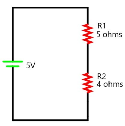
2. Find the voltage across the resistor R2 in the circuit.

Total resistance Rt = 5 + 4= 9 ohm
Voltage across resistance R2 = V.R2/Rt = 5 . 4/9 = 2.22 V
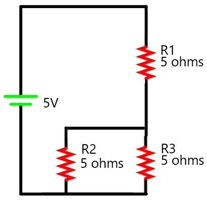
3. Find the voltage across the resistor R3 in the circuit.

Total resistance Rt = 5 + 5||5 = 5 + 5/2 = 7.5 ohm
Voltage across resistance R2 = V.R2/Rt = 5 . 2.5/7.5 = 1.667 V
Potential dividers

A simple circuit of passive components used to get a voltage that is a fraction of the input voltage is called a potential divider.
Read: Current division rule.
For example 3 where did you get the 2.5 from? Isn’t R2 5 ohms?
We have R2 and R3 5ohms each connected in parallel. so the effective resistance of the parallel combination becomes 2.5ohms.
To find the equivalent resistance of two resistors in parallel, you use 1/Rtotal = (1/R1 + 1/R2)
So for two 5 ohm resistors in parallel, 1/Rtotal = 1/5 + 1/5; 1/Rtotal = 2/5, hence Rtotal = 5/2 = 2.5.
Then you add that to the other 5 ohm resistor as you usually would for resistors in series